
Optical Measuring Machines
In this articleBreaking Data Silos with Networked MetrologyAnchoring Portable Metrology to the Digital ThreadValidating the Workflow for Your Shop FloorPre...
This shift feeds real-time geometric feedback directly into manufacturing execution systems (MES) and product lifecycle management (PLM) platforms, maintaining the digital thread for traceability and enabling digital twin synchronization. When part geometries change frequently, this integrated data flow is not just an advantage; it’s a necessity for competitive, lean operations.
Breaking Data Silos with Networked Metrology
A standalone optical measuring machine generates data, but value is created only when that data drives immediate decisions. In high-mix environments, inspection data often stagnates in proprietary formats, requiring manual transcription into quality logs—a process that introduces errors and delays corrective action for issues like tool wear or fixture drift.
Term Notes
A standalone optical measuring machine generates data, but value is created only when that data drives immediate decisions.
Anchoring Portable Metrology to the Digital ThreadLarge-scale metrology for assemblies—such as automotive weldments or aerospace structures—has historically been constrained…
Validating the Workflow for Your Shop FloorDeploying an optical measuring machine successfully requires more than verifying its volumetric accuracy on a spec sheet.
Preparing for a Connected Inspection StrategyFor engineers and quality managers evaluating this transition, the focus should be on your specific workflow needs.
The diagnostic question is straightforward: can your inspection system deliver tolerance-compliant reports to your MES or PLM before the next part reaches the workstation? Systems like the INSVISION AlphaVista series are engineered for this integration, enabling native export to standard CAD formats and API connectivity to factory software stacks.
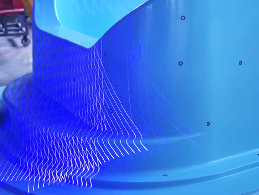
This turns volumetric scans and deviation heatmaps into actionable, audit-ready documentation without manual intervention, closing the loop between measurement and manufacturing execution.
Anchoring Portable Metrology to the Digital Thread
Large-scale metrology for assemblies—such as automotive weldments or aerospace structures—has historically been constrained by fixed CMM enclosures or laser trackers that require manual repositioning. This process risks alignment drift and breaks data continuity across a large part.
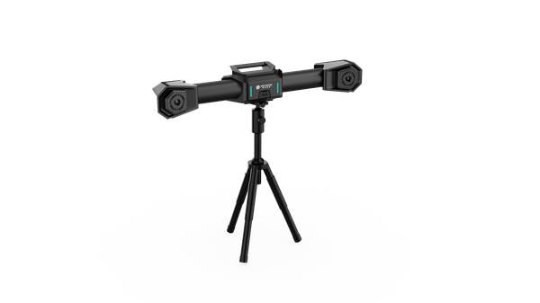
Portable optical systems have changed this paradigm, but their effectiveness hinges on maintaining a stable, metrology-grade coordinate frame across a dynamic shop floor. INSVISION’s X-Track system provides this backbone through high-precision binocular vision tracking. It allows for continuous coordinate alignment across wide areas, which is critical when measuring a 10-meter aircraft wing skin or a large machinery casting.
The system’s dual-mode switching between optical and marker-based tracking adapts to challenging surface reflectivity or occlusions, ensuring data coherence from the first scan to the final report and firmly anchoring portable metrology to the digital thread.
Validating the Workflow for Your Shop Floor
Deploying an optical measuring machine successfully requires more than verifying its volumetric accuracy on a spec sheet. It demands validating the entire inspection workflow under your specific conditions. Before scaling to a full production line, consider these parameters:
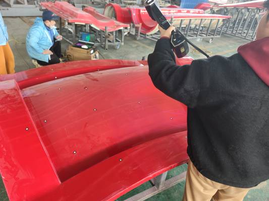
- Part & Environment: Document your typical part dimensions, material reflectivity, and ambient lighting conditions. For instance, measuring a composite panel differs significantly from scanning a machined aluminum block with oil residue.
- Integration Path: Confirm the system’s data outputs align with your existing software. Can it generate the GD&T reports your quality team requires and feed them directly to your MES dashboard?
- Site Verification: Systems perform differently on-site versus in a controlled lab. For large-scale tracking, verify the system’s stability across the entire measurement volume in your actual facility, accounting for floor vibration and thermal drift.
The transition from a pilot project to continuous production monitoring depends on matching the technology’s capabilities to these concrete boundary conditions. It ensures the optical measuring machine becomes a true data hub, not another isolated data island.
Preparing for a Connected Inspection Strategy
For engineers and quality managers evaluating this transition, the focus should be on your specific workflow needs. Start by mapping your current inspection cadence against your production takt time. Identify where delays occur—is it in data capture, analysis, or reporting?
When engaging with a supplier like INSVISION, be prepared to discuss:
- The specific part geometries and surface conditions you need to measure.
- Your required tolerance bands and reporting formats (e.g., ISO/ASME standards).
- The data connectivity needed between your inspection cell and your PLM or quality management system.
This preparation shifts the conversation from generic specifications to a solution engineered for your production reality, where the optical measuring machine functions as a critical data hub within a connected, responsive quality ecosystem.
Hangzhou Insvision Technology Co.,Ltd.
Address: Building 1, No. 1399 Liangmu Road, Yuhang District, Hangzhou, Zhejiang 311121, China