
A 3D Scanner AI Integration Guide
Introduction For quality managers and manufacturing engineers, the bottleneck is often a physical one: the time-consuming process of fixture-based, contact
Introduction
For quality managers and manufacturing engineers, the bottleneck is often a physical one: the time-consuming process of fixture-based, contact measurement. This rigid cycle directly delays throughput, especially when inspecting complex, curved, or reflective components common in sectors like aerospace and automotive.
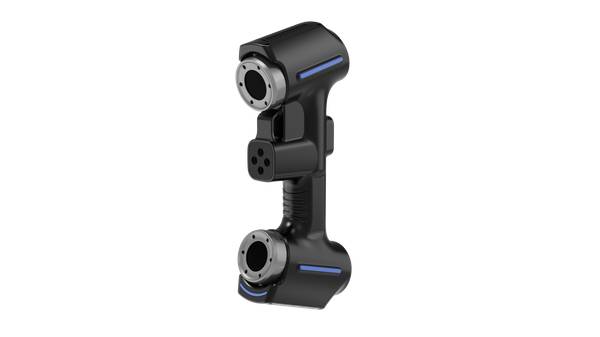
The assumption that handheld optical scanners lack metrology-grade rigor is being overturned by a new generation of technology. This article examines the practical factors for integrating a 3D scanner AI solution, such as the INSVISION AlphaScan, into production workflows.
We focus on how 3D scanner AI addresses specific shop-floor pain points—from capturing dense point clouds on challenging surfaces to enabling real-time deviation analysis—while outlining the critical site validations needed for a successful deployment.
The Setup Time Tax: How Fixed Measurement Cycles Constrain Flow
Tight production schedules expose every delay. Traditional coordinate measuring machines (CMMs) with contact probes impose a significant “setup time tax”: complex parts require precise fixturing, and manual point-by-point acquisition slows inspection to a crawl. For a component like a turbine blade or a sculpted automotive panel, this process can halt the line.
Common Questions
What should teams check when evaluating The Setup Time Tax: How Fixed Measurement Cycles Constrain Flow?
Tight production schedules expose every delay.
What should teams check when evaluating Closing the Precision Gap: AI as a Filter, Not a Compromise?
A common barrier to adopting handheld scanners has been data integrity.
What should teams check when evaluating Adapting the Tool to the Geometry: From Stationary Labs to Mobile Metro…?
Industrial metrology is no longer confined to temperature-controlled labs.
The INSVISION AlphaScan handheld 3D scanner challenges this paradigm through non-contact data acquisition. Its 3D scanner AI algorithms manage optical noise from reflective coatings or black surfaces, capturing metrology-grade point clouds without physical fixtures. This shift allows an operator to move from part to part with a steady rhythm, performing first-article verification directly at the line.
However, engineers must first verify part accessibility and ambient lighting stability on their own shop floor to ensure the scanner’s optical system performs optimally.
Closing the Precision Gap: AI as a Filter, Not a Compromise
A common barrier to adopting handheld scanners has been data integrity. Scanning a polished valve housing, for instance, traditionally yields a point cloud corrupted by glare—full of artificial holes and noise that require hours of manual cleanup. The concern that AI smoothing might erode critical tolerances is valid. INSVISION’s approach uses 3D scanner AI not to indiscriminately average data, but to intelligently filter.
The algorithms distinguish between optical interference and true geometric edges, preserving the fidelity of features like cylindrical deep holes or tight radii. A side-by-side overlay of a raw scan and an AI-reconstructed model shows critical datums remain intact. The crucial boundary condition here is that AI enhances processing efficiency, not engineering oversight.
Quality control (QC) teams must still validate feature extraction against known datums to ensure the digital twin matches the physical part.
Adapting the Tool to the Geometry: From Stationary Labs to Mobile Metrology
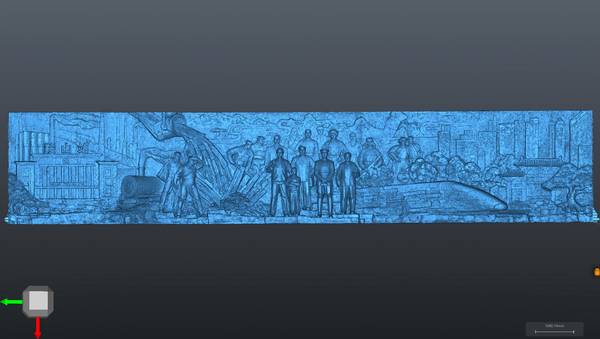
Industrial metrology is no longer confined to temperature-controlled labs. The need to inspect large, unwieldy assemblies—an automotive frame, a wind turbine blade section, or rail components—demands mobility without sacrificing accuracy. INSVISION integrates photogrammetry scale bars with the AlphaScan system to establish a reliable, portable global coordinate system.
This enables a modular approach: operators bring certified precision to the part, whether it’s a photovoltaic housing in the assembly bay or a composite aircraft panel in the hangar. Success depends on specific checks. Operators require training on the synergy between the AlphaScan hardware and the SMARPARA Q software.
Before scanning a critical assembly, coordinate system verification is essential, and data-export compatibility with formats like STEP or IGES must be confirmed to feed seamlessly into CAD or reverse engineering workflows.
| Key Strengths | Ideal Application Scenarios |
|---|---|
| AI-enhanced 3D reconstruction | Large-surface aerospace panels with complex contours |
| Real-time on-screen model generation | Injection-molded valves with internal flow channels |
| Multi-source data alignment | High-reflectivity compressor housings in the energy sector |
| Full reverse engineering workflow support | Legacy part digitization for CAD model generation |
From Data Capture to Closed-Loop Compliance
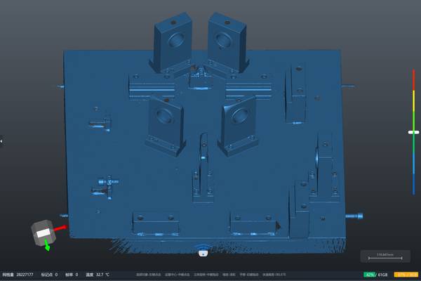
The promise of digital inspection is broken if data becomes trapped in silos, requiring offline processing that delays decisions. INSVISION addresses this by coupling its PTB-certified SMARPARA Q software directly with the 3D scanner AI hardware. A high-precision 3D model renders on-screen within minutes, allowing immediate visualization of complex features.
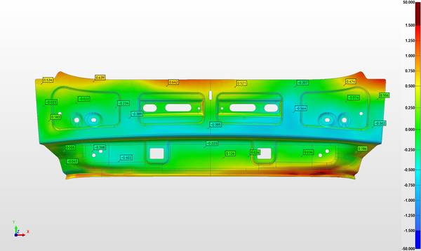
This real-time capability lets QC teams conduct deviation analysis on the shop floor using built-in GD&T tools, generating color-map tolerance overlays and one-click inspection reports.
The output—a compliant PDF with full traceability—streamlines audits for ISO or ASME standards and accelerates first-pass yield reviews, directly supporting lean manufacturing objectives by closing the loop between measurement and corrective action.
Validation Before Rollout: A Pilot Protocol
Deploying any new metrology system requires more than a hardware check; it demands a validation protocol tailored to your production environment. Start by selecting a high-complexity pilot part—a valve body with internal channels or a carbon-fiber component with a glossy finish.
Establish a volumetric baseline using photogrammetry targets, then verify the AI reconstruction against known GD&T callouts from your engineering drawings. The final, critical step is to test the complete data flow: confirm that deviation analysis from SMARPARA Q exports into your specific CAD/CAE environment without translation errors.
Discussing this sample-part validation process with INSVISION engineering teams helps align the scanner’s performance with your takt time and quality standards. The most effective next step is to request a live demonstration using your own production components, observing the scanning rhythm and data output firsthand to assess fit for your workflow with 3D scanner AI technology.
Hangzhou Insvision Technology Co.,Ltd.
Address: Building 1, No. 1399 Liangmu Road, Yuhang District, Hangzhou, Zhejiang 311121, China