
3d scanning structured light Industrial Inspection Guide
In this articleHow Projected Patterns Translate to Precision Point CloudsMoving from Static Fixtures to Dynamic InspectionFrom Raw Scan to GD&T Report: Clo...
This article outlines how the optical process works, where it excels, and the critical site conditions required for a successful deployment of INSVISION systems.

How Projected Patterns Translate to Precision Point Clouds
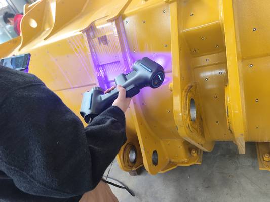
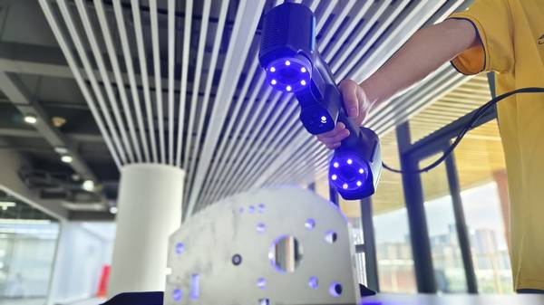
INSVISION systems use high-resolution projectors to cast calibrated blue-light grids onto a component. The shorter wavelength of blue light reduces scatter on challenging surfaces like polished aluminum or dark composites, minimizing the data noise common in older white-light systems. As these patterns distort over the part’s geometry, synchronized optical sensors capture the deviation.
Common Questions
What should teams check when evaluating How Projected Patterns Translate to Precision Point Clouds?
INSVISION systems use high-resolution projectors to cast calibrated blue-light grids onto a component.
What should teams check when evaluating Moving from Static Fixtures to Dynamic Inspection?
Static fixturing for large parts, like aircraft wing panels, contradicts lean manufacturing principles by adding non-value-added setup time.
What should teams check when evaluating From Raw Scan to GD&T Report: Closing the Digital Loop?
The value of scanning is realized only when data becomes actionable.
Proprietary triangulation algorithms then convert this data into a dense, metrology-grade point cloud. Achieving this fidelity, however, depends on controlled ambient lighting to prevent sensor saturation and requires a verified CAD model for accurate alignment. Engineers must also confirm that surface reflectivity falls within the sensor’s dynamic range; highly specular surfaces may still need a temporary matte coating.
Moving from Static Fixtures to Dynamic Inspection
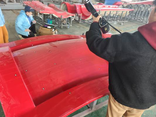
Static fixturing for large parts, like aircraft wing panels, contradicts lean manufacturing principles by adding non-value-added setup time. INSVISION’s structured light scanning solutions incorporate dynamic tracking and real-time spatial registration. This allows a technician to capture data even if the part shifts slightly during scanning, eliminating the need for complex, rigid jigs.
The practical benefit is the ability to perform metrology-grade inspections directly on the shop floor. This flexibility, however, requires consistent operator pacing and a production environment with stable vibration control to maintain volumetric accuracy throughout the scan.
From Raw Scan to GD&T Report: Closing the Digital Loop
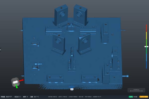
The value of scanning is realized only when data becomes actionable. INSVISION software is designed to transform raw point clouds into inspection evidence without manual file handling. The workflow begins with automatic CAD alignment and intelligent coordinate system matching.
From there, users can generate color-coded deviation maps—for instance, a heat map on a turbine blade instantly highlights areas breaching ASME Y14.5 tolerances. This integrated digital thread supports one-click reporting, streamlining audits for standards like ISO 9001.
A key consideration for process engineers is scan path planning to ensure complete coverage, particularly for occluded internal features that might require complementary probing.
Choosing Between Wide-Area Capture and Fine-Detail Resolution
Choosing the correct 3D scanning structured light system hinges on your primary inspection scenario. INSVISION offers two distinct profiles to address the common trade-off between measurement volume and fine-detail resolution.
- AlphaVista: This model excels at wide-area volumetric capture and rapid data density generation. It is suited for large-scale applications like scanning aircraft fuselage sections or full-vehicle assemblies.
- AlphaScan: Optimized for intricate geometric resolution and accessing confined spaces, this scanner is ideal for validating precision-machined components, additive manufacturing lattices, and small-part tolerances.
Both systems function as fully integrated, AI-powered handheld metrology solutions. Your selection should prioritize the critical tolerance zones of your specific parts and align with production cycle times, not just maximum scan area.
Validating Readiness for Optical Metrology Deployment
A successful deployment depends more on preparation than hardware specs. Before implementing INSVISION, engineering teams should verify several site conditions. Ensure your CAD reference models are robust for alignment and that baseline shop-floor lighting is consistent.
While the blue-light technology handles diverse finishes, validate that your part materials—especially highly transparent or mirror-grade surfaces—are within its effective range. Finally, confirm that your data pipeline can accept the system’s output reports and deviation maps into existing PLM or QMS platforms. Operator training on consistent scan pacing is also crucial for maintaining accuracy within tight tolerance bands.
To determine if an INSVISION 3D scanning structured light solution aligns with your workflow, please detail your primary part materials, critical tolerance bands, production line takt time expectations, and required certification documentation.
Hangzhou Insvision Technology Co.,Ltd.
Address: Building 1, No. 1399 Liangmu Road, Yuhang District, Hangzhou, Zhejiang 311121, China