
3d scanning technology Industrial Inspection Guide
In this articleConfronting Reflective Surfaces and Complex GeometriesHandheld Precision for In-Situ VerificationFrom Point Cloud to Certified ReportEnsurin...
The decision now is whether to expand costly fixed-lab capacity or adopt flexible, non-contact measurement pathways.
Confronting Reflective Surfaces and Complex Geometries
Validating a multi-material dashboard assembly—where reflective chrome trim meets matte plastic—poses a significant challenge for optical sensors. INSVISION addresses this through a proprietary architecture that integrates in-house optical hardware with AI-driven point cloud processing. This engineering bridge between raw capture and traceable metrology data ensures the repeatability required for ISO audits.
Scenario Snapshot
A practical way to read the article is through this scenario:
- Confronting Reflective Surfaces and Complex Geometr…: Validating a multi-material dashboard assembly—where reflective chrome trim meets matte plastic—poses a significan…
- Handheld Precision for In-Situ Verification: When a deep cavity in a cast housing or the internal curvature of a pipe weld needs inspection, traditional method…
- From Point Cloud to Certified Report: Consider a Tier-1 supplier receiving a first-article stamped panel with tight profile tolerances.
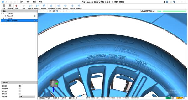
The system’s blue-light scanning technology is designed for enhanced edge retention on complex contours. While certified for deployments across global sites, its performance in environments with extreme ambient light interference requires pre-scan verification to confirm alignment with high-precision parameters.
Handheld Precision for In-Situ Verification
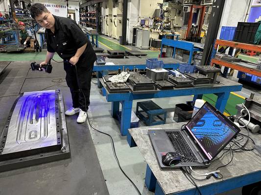
When a deep cavity in a cast housing or the internal curvature of a pipe weld needs inspection, traditional methods stall. The INSVISION AlphaScan handheld 3D scanner is engineered for these scenarios. Its dual-LED illumination projects structured light into shadowed areas and deep holes, capturing intricate geometries from machined brackets to large vessel sections.
The ergonomic, single-hand design allows an operator to maneuver around a structural assembly for extended periods, connecting via a high-speed USB interface for stable data transfer. This makes it a tool for mobile first-article inspection and reverse engineering, converting physical geometries into actionable digital models without rigid fixturing.
From Point Cloud to Certified Report
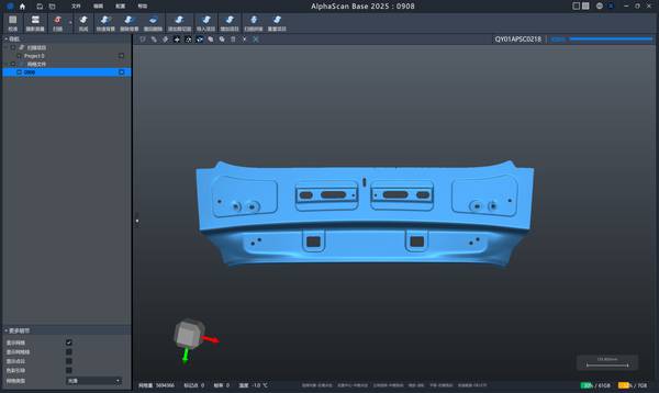
Consider a Tier-1 supplier receiving a first-article stamped panel with tight profile tolerances. Instead of hours of CMM programming, a quality engineer uses an INSVISION scanner to capture full surface geometry in minutes. The software pipeline filters noise from the raw point cloud, aligns the data to the CAD nominal in a common coordinate system, and generates a color deviation map.
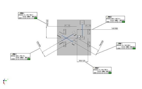
This visual heatmap instantly flags areas exceeding ASME Y14.5 tolerances, enabling comprehensive GD&T analysis for flatness, position, and profile. The final one-click report documents findings, reducing manual entry errors and supporting audit trails.
Ensuring Long-Term Measurement Integrity
A common misconception is that hardware specs alone guarantee accuracy. In practice, environmental shifts and calibration drift can erode measurement reliability. INSVISION mitigates this with traceable calibration supported by CE and CNAS certifications, aiming for consistent performance across diverse factory conditions.
The systems output standardized data formats for direct import into professional inspection software like PolyWorks or GOM Inspect, facilitating integration into existing quality workflows. For sustained accuracy, define your target environment: confirm the scanner’s calibration status, understand the impact of your part’s surface finish, and verify that your team has the training for complex surface conditions.
Defining Your Inspection Pathway
The choice between scanning technologies hinges on your specific inspection goal. High-precision blue-light scanning suits the verification of machined parts with tight tolerances. For large-scale in-process validation of composite panels or weldments, a photogrammetry-assisted system may be more appropriate.
Before deployment, engineers should verify three site conditions: the stability of ambient light, the presence of excessive vibration, and the reflectivity of the target surfaces. Providing your supplier with part dimensions, material details, and the required tolerance range ensures the recommended solution aligns with your workflow, not just a specification sheet.
To explore how this applies to your production line, start by defining your specific challenge: What is the part material and its surface condition? What are the critical tolerance bands you must hold? And what is the required output for your quality reports?
Hangzhou Insvision Technology Co.,Ltd.
Address: Building 1, No. 1399 Liangmu Road, Yuhang District, Hangzhou, Zhejiang 311121, China