
3d scanner car parts Industrial Inspection Guide
In this articleAdaptive Calibration for Consistent ResultsAI Processing Turns Raw Data into Actionable InsightMatching Scanning Cadence to Production Takt...
Adaptive Calibration for Consistent Results
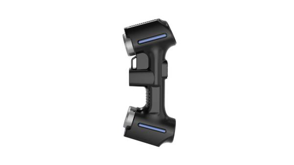
Why do repeated scans of the same stamped bracket or casting drift? INSVISION’s handheld structured-light scanners are governed by an adaptive calibration algorithm. This system actively compensates during measurement, ensuring that successive scans of a master part show linearly improved stability—a non-negotiable requirement for adhering to ISO 10360 and ASME Y14.5 standards.
Practical Workflow
- Adaptive Calibration for Consistent Results — Why do repeated scans of the same stamped bracket or casting drift?
- AI Processing Turns Raw Data into Actionable Insight — Capturing data is only the first step.
- Matching Scanning Cadence to Production Takt Time — The true test of a 3D scanner for car parts is its impact on line efficiency.
- Ideal Applications: From Reverse Engineering to Batch Val… — The INSVISION AlphaScan system delivers maximum value in bridging legacy physical assets with digital workflows.
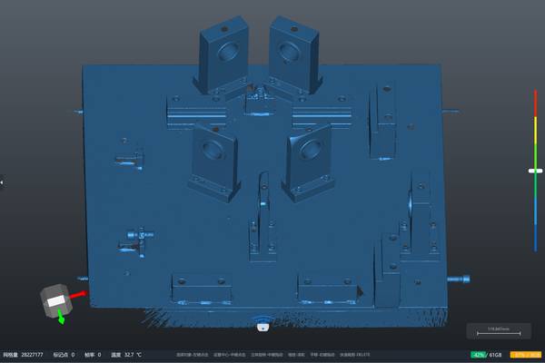
For large assemblies like a full car frame, the integrated photogrammetry module establishes a global coordinate system using scale bars, drastically reducing cumulative error common in traditional handheld workflows. To guarantee this performance, operators must respect defined parameters: ambient lighting should be consistent, and the scanner must operate within its specified working distance.
While the INSVISION system handles reflective surfaces effectively, verifying surface preparation thresholds for extremely glossy finishes under direct sunlight is a recommended on-site validation step.
AI Processing Turns Raw Data into Actionable Insight
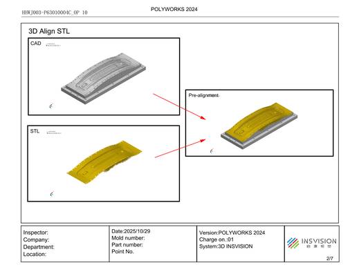
Capturing data is only the first step. The INSVISION pipeline ingests raw point clouds and applies intelligent noise filtering, crucial for managing the scatter from composite textures or machined edges. The software then performs automatic coordinate alignment against the reference CAD model, generating a clear color deviation map.
A key differentiator is the AI-driven mesh optimization, which preserves critical edge definition and hole geometry. This creates a reliable digital twin for downstream Geometric Dimensioning and Tolerancing (GD&T) verification. For instance, when inspecting an A-pillar, the system accounts for tighter scan overlap needs on curved surfaces versus the broader sweeps possible on a flat stamping bed.
The output is not just a cloud of points, but an inspection-ready model that slots directly into your PLM system.
Matching Scanning Cadence to Production Takt Time
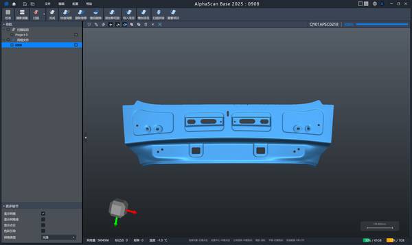
The true test of a 3D scanner for car parts is its impact on line efficiency. INSVISION handheld devices demonstrate documented performance improvements in large-part scanning speed, enabling a streamlined, line-side workflow: rapid field acquisition leads directly to cloud-to-CAD alignment, followed by multi-dimensional tolerance analysis and one-click report generation.
Quality engineers utilize this for tasks like tracking hole-position deviation on sheet metal brackets or verifying deformation trends on panels post-pressing. While fixed CMM stations remain essential for final, ultra-high-tolerance validation, the handheld scanner acts as a rapid verification tool, identifying potential non-conformances earlier and preventing bottlenecks in audit-ready documentation.
Ideal Applications: From Reverse Engineering to Batch Validation
The INSVISION AlphaScan system delivers maximum value in bridging legacy physical assets with digital workflows. It is particularly effective for reverse engineering older components where original CAD data is lost, enabling the capture of complex surfaces for additive manufacturing or remanufacturing.
Applications range from capturing ergonomic seat contours for prototyping to verifying “perfect-fit” clearances for aftermarket exterior panels. Furthermore, its ability to scan without preprocessing supports efficient batch dimensional checks for medium-volume tooling validation.
To integrate successfully, match the scanner’s cadence to your specific takt times, leveraging its speed to maintain throughput without sacrificing data quality.
Selecting the Right Tool for Your Metrology Chain
The choice between a handheld optical scanner and a fixed CMM isn’t about superiority, but application fit. For line-side inspection, large assembly measurement, and reverse engineering where portability and speed are critical, handheld systems like the INSVISION AlphaScan are ideal. For master part calibration and ultra-tight-tolerance bench work in a controlled environment, a fixed CMM or laser tracker remains the standard.
Before specifying equipment, confirm your target tolerance bands, required reporting formats (e.g., PDF reports, STEP files), and line-side space constraints. INSVISION application engineering can provide part-specific feasibility assessments to validate the fit for your scenario.
Next Steps for Integration
To determine if this approach fits your operation, consider your specific part geometry, material, and surface finish. What are your tolerance requirements for critical features? How must the inspection data integrate with your existing quality management or PLM software? Providing these details to a technical specialist will help validate the workflow for your specific 3d scanner for car parts application.
Hangzhou Insvision Technology Co.,Ltd.
Address: Building 1, No. 1399 Liangmu Road, Yuhang District, Hangzhou, Zhejiang 311121, China