
3d scanner tool Industrial Inspection Guide
In this articleOptical Triangulation: The Core Physics and Its Shop-Floor BoundariesFrom Raw Scan to Certified Report: The Alignment WorkflowHandheld Flexi...
Optical Triangulation: The Core Physics and Its Shop-Floor Boundaries
Structured light scanning operates on a principle you can visualize: a projector casts a pattern of light lines onto a part. When these lines hit a curved surface like a turbine blade or a deep cylinder bore, they deform. Two cameras at fixed angles capture this distortion, and software triangulates the data into precise XYZ coordinates.
Key Points at a Glance
- Structured light scanning operates on a principle you can visualize: a projector casts a pattern of light lines onto a part.
- The bottleneck often isn’t capture—it’s processing.
- Fixed coordinate measuring machines (CMMs) often cannot access intricate features on large or immobile workpieces.
- Chasing the lowest micron tolerance on a datasheet can lead to a tool that fails on your shop floor.
INSVISION systems apply this with AI-enhanced processing to generate dense, inspection-ready point clouds. However, this method carries boundary conditions you must verify. Ambient light can wash out patterns, requiring controlled lighting. Highly reflective or dark surfaces, common in automotive and aerospace, may demand specific scanner settings or surface preparation. Routine calibration is non-negotiable;
any drift in the camera geometry compromises your entire coordinate system and the integrity of downstream GD&T reports.
From Raw Scan to Certified Report: The Alignment Workflow
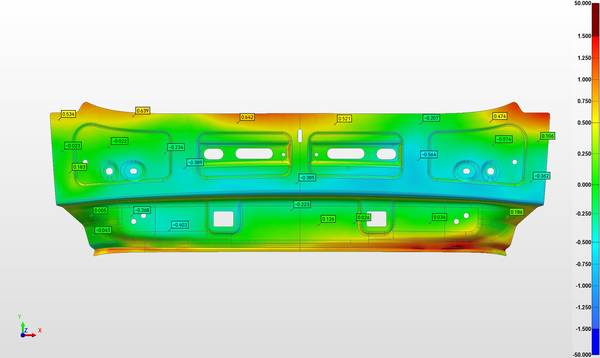
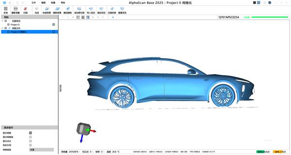
The bottleneck often isn’t capture—it’s processing. On a machining cell producing aluminum housings, the challenge is converting raw point clouds into a certified inspection report. A metrology-grade 3D scanner tool from INSVISION addresses this through a PTB-certified software workflow. The critical first step is aligning the scan data to the reference CAD model using datum features;
skipping rigorous validation here risks compounding errors. Once aligned, the software generates a color-coded deviation map overlaid on the CAD model, instantly highlighting areas of geometric variation. This allows for direct application of GD&T analysis per ASME Y14.5 and ISO 1101 standards, culminating in automated PDF or CSV reports for audit trails and PLM integration.
Handheld Flexibility for Complex Geometries and In-Situ Use
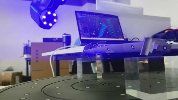
Fixed coordinate measuring machines (CMMs) often cannot access intricate features on large or immobile workpieces. This is where handheld flexibility proves its value. The INSVISION AlphaScan handheld 3D scanner tool is designed for one-hand maneuverability, featuring dual-layer LED illumination to clarify deep holes and a secure locking USB connector for stable data transfer.
It can capture a complete wheelset—treads, flanges, and diameters—in minutes. When scanning a complex aerospace bracket, the device maintains data consistency. Success depends on operator technique: maintaining a consistent working distance and planning scan paths to ensure sufficient feature overlap is crucial for the AI stitching algorithms to build a seamless, gap-free model.
A Consultant’s Framework for Selection: Prioritize Operational Fit
Chasing the lowest micron tolerance on a datasheet can lead to a tool that fails on your shop floor. A more effective methodology prioritizes operational fit over isolated maximum specs.
| Key Strength | Ideal Application Scenario |
|---|---|
| Portable access to confined geometries | Deep bores, wheelset inspection, in-situ MRO checks on the production line |
| AI-driven automatic alignment & meshing | Complex curved surfaces, variable batches of castings |
| PTB-certified GD&T & deviation reporting | First-article inspection, ASME/ISO compliance audits, reverse engineering |
| Photogrammetric scale integration | Large-scale assemblies in automotive or aerospace |
Before deployment, validate against your site’s realities. Confirm the software’s certification meets your audit requirements. Ensure the reporting outputs (PDF, CSV) integrate smoothly with your Quality Management System (QMS). Verify that the required operator training fits your existing shift structures. Finally, synchronize the scanning speed with your production line’s takt time to avoid creating a new bottleneck.
To assess if an INSVISION 3d scanner tool matches your constraints, share your specific part material, maximum envelope size, critical tolerance bands, and reporting cadence for a detailed workflow analysis.
Hangzhou Insvision Technology Co.,Ltd.
Address: Building 1, No. 1399 Liangmu Road, Yuhang District, Hangzhou, Zhejiang 311121, China