
3D Scanning Reference Points
Master 3D scanning reference points for handheld metrology. Learn placement strategies to ensure consistent alignment on the production floor
Surface reflectivity, deep undercuts, or obstructed datums on a large casting or a contoured aerospace bracket can break optical continuity, introducing alignment artifacts that corrupt the final deviation report.
This article examines the role of reference points in modern inspection, detailing how to match point strategy to part complexity and how INSVISION‘s AlphaScan system approaches continuous alignment to bridge the gap between handheld mobility and lab-grade reliability.

Why Reference Point Strategy Is Now a Primary Engineering Consideration
The transition from tactile coordinate measuring machines (CMMs) to optical scanning has fundamentally changed the source of measurement error. Where a CMM probe follows a programmed path in a known volume, a handheld scanner must dynamically relate countless discrete capture positions to a single, unified coordinate system. This process of spatial registration depends entirely on 3D scanning reference points.
Scenario Snapshot
A practical way to read the article is through this scenario:
- Why Reference Point Strategy Is Now a Primary Engin…: The transition from tactile coordinate measuring machines (CMMs) to optical scanning has fundamentally changed the…
- Maintaining Metrology-Grade Alignment in Freehand M…: Traditional workflows often required an operator to pause and re-register the scanner after moving around a large…
- Transforming Point Clouds into Actionable Complianc…: Capturing an accurate point cloud is only the first step;
Features like datum targets, machined edges, or fiducial markers act as mathematical anchors.
Without stable reference, scans of a turbine blade’s leading and trailing edges, for example, cannot be accurately stitched, turning a single point cloud into a fragmented dataset. Engineers must now verify boundary conditions before scanning: will the surface finish on a sand-cast part provide enough texture for feature recognition, or will a polished automotive die reflect light away from critical edges?
The stability of these anchors dictates whether a final color map reveals true part deviation or mere scanning artifact.
Maintaining Metrology-Grade Alignment in Freehand Motion
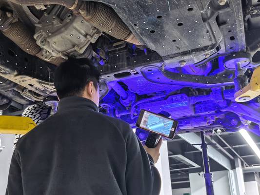
Traditional workflows often required an operator to pause and re-register the scanner after moving around a large part, breaking the inspection rhythm and introducing potential error with each stop. INSVISION addresses this with the AlphaScan’s optical tracking architecture, designed to stabilize spatial anchors dynamically.
By combining a blue laser line array with AI-driven point-cloud processing, the system allows an operator to maintain a continuous measurement stream with micron-level accuracy while freely maneuvering around a complex weldment or engine block. The integrated software manages real-time coordinate alignment, automatically recognizing and locking onto physical 3D scanning reference points without manual intervention.
To ensure this high-fidelity data stream remains intact in electrically noisy production cells, the device uses a secured, high-speed USB connection rather than wireless, preventing signal drop-offs. The result for lean manufacturing is consistent alignment across multi-feature parts without the latency of static repositioning.
Transforming Point Clouds into Actionable Compliance Reports
Capturing an accurate point cloud is only the first step; its value is realized in a seamless software pipeline that delivers auditable results. Once 3D scanning reference points are captured and aligned, the INSVISION software imports the data for immediate processing.
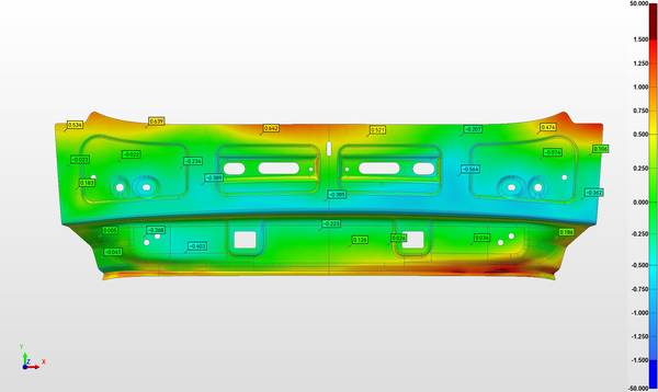
The system executes automated alignment against the CAD master, instantly generating intuitive color deviation maps that visualize geometric errors right on the scanner’s touchscreen.
This allows for first-article verification to be conducted at the machining center, not a remote quality lab. The built-in inspection module then conducts rigorous tolerance analysis, checking dimensions against ASME Y14.5 and ISO GPS standards. A user can generate a detailed compliance report with one click, outputting the dimensional validation required for quality audits.
This closed-loop workflow accelerates the feedback cycle to machining, ensuring that the scanner’s micron-level accuracy directly translates to production decisions.
Matching Your Part Profile to Handheld Metrology
Handheld metrology offers necessary flexibility when part geometry undermines fixed CMM probing, but only if the system manages reference points reliably. Not all parts are equal. Engineers should first assess datum accessibility: are the primary datum targets on a large composite tooling plate obscured by ribs or undercuts?
A robust reference point strategy must maintain volumetric accuracy without forcing excessive surface preparation like spray or target placement in impossible locations.
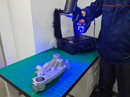
INSVISION AlphaScan is engineered for these scenarios, using metrology-grade scanning to stabilize alignment for challenging parts—from castings with irregular datum targets to additive-manufactured components requiring full-surface validation. Its workflow provides immediate visual feedback through live deviation maps, aiding rapid error identification.
Before purchase, buyers must confirm the software exports native scan data formats compatible with their existing QMS or digital twin platforms, ensuring the inspection process integrates into Industry 4.0 production rhythms.
Validating the Workflow for Your Production Environment
Adopting a handheld metrology solution requires more than a hardware specification check; it demands a validation of the entire inspection pipeline under your specific conditions. Begin by identifying a representative sample part—an aerospace bracket with tight tolerances or a stamped automotive panel with complex curvature.
The critical test is not just raw accuracy, but the system’s ability to maintain consistent alignment through a full, uninterrupted scan sequence, especially around occluded reference features.
Observe the data processing steps: how quickly does the software transition from raw point cloud to a preliminary deviation map on the shop floor? Finally, verify the report output meets your quality department’s standards for format and detail.
Hangzhou Insvision Technology Co.,Ltd.
Address: Building 1, No. 1399 Liangmu Road, Yuhang District, Hangzhou, Zhejiang 311121, China