
3d scanner for reverse engineering Selection Guide
In this articlePrecision Engineered for Unstable EnvironmentsFrom Point Cloud to Verified CAD in a Certified WorkflowValidation in High-Stakes Sectors: Aut...
INSVISION addresses this by integrating PTB-certified software with hardware like the AlphaVista series, which captures 7,100,000 measurements per second, to bridge the gap between a physical part and a reliable digital twin for first-article inspection and beyond.
Precision Engineered for Unstable Environments
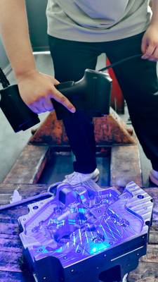
A common assumption is that scanning bottlenecks are hardware-limited. In practice, unstable data transfer during a single-pass scan of a complex item like a motorcycle cylinder head can corrupt an entire dataset. INSVISION engineers its systems from the ground up, integrating AI-powered 3D vision and proprietary algorithms directly with the hardware.
Scenario Snapshot
A practical way to read the article is through this scenario:
- Precision Engineered for Unstable Environments: A common assumption is that scanning bottlenecks are hardware-limited.
- From Point Cloud to Verified CAD in a Certified Wor…: The true value of a 3D scanner for reverse engineering is proven downstream.
- Validation in High-Stakes Sectors: Automotive and E…: How do you ensure a reverse-engineered part meets the stringent standards of automotive or energy applications?
This focus ensures real-time alignment and noise suppression, which is why the INSVISION AlphaScan platform employs a high-speed USB fixed-knob design. This isn’t merely a connector; it’s a stability feature for maintaining consistent point cloud density when scanning intricate geometries, a non-negotiable requirement for successful surface fitting later in the reverse engineering workflow.
From Point Cloud to Verified CAD in a Certified Workflow
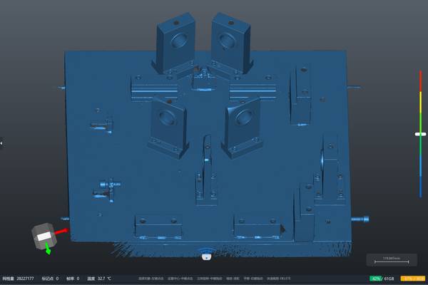
The true value of a 3D scanner for reverse engineering is proven downstream. INSVISION’s PTB-certified software ecosystem anchors the process, transforming raw scan data into actionable engineering data. The workflow moves from data processing and domain segmentation directly to surface fitting and CAD conversion.
For instance, after scanning a large cast energy component, the software allows for multi-source data alignment and built-in GD&T analysis. This replaces manual approximation with verified tolerances, enabling users to generate one-click deviation reports in mainstream CAD formats.
The result is a closed loop: geometry is validated against design intent immediately after capture, reducing the iterative loops that plague legacy processes.
Validation in High-Stakes Sectors: Automotive and Energy
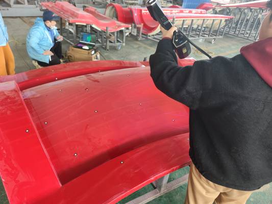
How do you ensure a reverse-engineered part meets the stringent standards of automotive or energy applications? Validation happens through precise application. INSVISION systems are deployed to capture everything from complex motorcycle engine brackets and fairings to large, weathered energy equipment components.
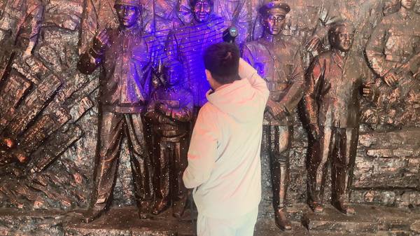
The generated point cloud integrates directly into quality control for immediate deviation analysis against a reference model. Achieving repeatable results, however, requires respecting boundary conditions. For high-reflectivity surfaces common in energy sectors, applying a temporary matte coating is a necessary step for optimal data acquisition.
Similarly, leveraging features like 50 cross blue laser lines in a controlled lighting environment ensures accurate capture of deep-hole structures. Establishing operator checkpoints during the scan safeguards data integrity for all downstream validation.
Deploying with Confidence: A Procurement and Validation Guide
With manufacturing cycles compressing, validating your investment in a 3D scanner for reverse engineering demands a focus on metrology traceability and integration. Procurement should start by confirming that system calibration is aligned with PTB or equivalent standards, ensuring reliability for critical tasks. Next, assess software compatibility;
verify support for standard 3D data formats (like STEP, IGES) to ensure seamless integration into existing PLM or CAM systems without data fragmentation. INSVISION structures its training to equip technicians to master the full workflow—from handling varied surface conditions to executing domain segmentation. Beyond deployment, continuous software updates align with evolving standards.
To determine the optimal configuration for your operation, consider your specific part materials, tolerance bands, and reporting format requirements. What are the typical surface conditions and size constraints of the components you need to digitize with your 3D scanner for reverse engineering?
Hangzhou Insvision Technology Co.,Ltd.
Address: Building 1, No. 1399 Liangmu Road, Yuhang District, Hangzhou, Zhejiang 311121, China