
CAD-Centric Scanner Workflow for CAM
Resolve shop-floor inspection delays with an automated scanner CAD CAM workflow. See how CAD alignment improves metrology confidence
Introduction
When a first-article inspection queue stalls a machining cell, the root cause is often traceable to a single, manual step: aligning a physical part to its CAD model. This foundational bottleneck in the scanner CAD CAM workflow forces a costly compromise between inspection speed and metrology-grade confidence.
Under lean takt times and standards like ASME Y14.5, the delay in generating reliable deviation data directly impacts downstream CAM programming and toolpath correction.
This article examines why manual registration fails for complex geometries, how automated CAD alignment bridges the gap, and what technical boundaries determine a scanner’s suitability for CAM-ready workflows.
The Registration Bottleneck: Where Manual Processes Break Down
In high-mix environments, the manual selection of datum points to register a scanned part against its nominal CAD file is the critical constraint. Technicians approximating positions on complex surfaces can miss deviations in deep holes or internal cavities, creating unreliable data for CAM-based re-machining. This friction is compounded by fixture changeover times and CMM scheduling conflicts.
Key Points at a Glance
- In high-mix environments, the manual selection of datum points to register a scanned part against its nominal CAD file is the critical constrain…
- Direct, automatic alignment of scan data to the original CAD model is non-negotiable for an efficient workflow.
- Determining if a handheld scanner CAD CAM workflow is viable depends on matching the hardware’s capabilities to specific part challenges and tol…
- The final value of a scanner CAD CAM integration is a closed-loop process where scan data directly informs manufacturing correction.
The result is a widening gap between the as-built part and the digital twin, delaying the feedback loop essential for maintaining production flow.
For a scanner CAD CAM process to be effective, it must eliminate this manual alignment step to provide a direct, trustworthy link between physical measurement and digital design intent.
Automated Alignment: The Linchpin for Reliable Data
Direct, automatic alignment of scan data to the original CAD model is non-negotiable for an efficient workflow. Without it, registration drift and manual point-cloud stitching introduce cumulative error, especially on large assemblies or parts with reflective coatings. This turns quality inspection into a lengthy data reconstruction project. INSVISION addresses this by driving the inspection process from the CAD model itself.
The system uses photogrammetric scale bars to establish a stable global coordinate system, bypassing manual registration.
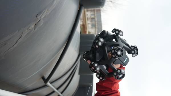
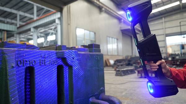
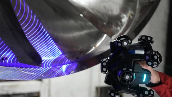
A high-precision dual-axis scanning galvanometer then projects the CAD data as visible green laser contours directly onto the workpiece, grounding the inspection in the correct coordinate system from the start. For challenging features like deep internal cavities or dark surfaces, dual cameras and precision algorithms capture fine details, generating intuitive chromatic deviation maps.
Matching Scanner Capability to Part Geometry and Tolerance
Determining if a handheld scanner CAD CAM workflow is viable depends on matching the hardware’s capabilities to specific part challenges and tolerance bands. Not all scanners perform equally on all surfaces or geometries. Key evaluation criteria include the ability to maintain alignment on dark or reflective surfaces without markers, and the precision to capture deep internal features.
INSVISION’s technology is applied across several demanding scenarios:
- Aerospace MRO Component Inspection: Automatic CAD alignment enables rapid pass/fail validation against design intent for turbine blades or structural brackets.
- Energy Sector Valve Inspection: The dual-camera system captures intricate internal geometries, R-corners, and sealing surfaces that are inaccessible to manual probes.
- Automotive OEM Tooling Validation: Green laser projection provides clear contour guidance on high-reflectivity mold surfaces, while photogrammetry maintains volumetric accuracy across large body panels.
The decision hinges on verifying the scanner’s stated metro-grade accuracy (for INSVISION, confirmed up to 0.02mm and compliant with CE, FCC, and CNAS standards) against your tightest tolerance bands in a real-world test.
Closing the Loop: From Deviation Map to CAM-Ready Output
The final value of a scanner CAD CAM integration is a closed-loop process where scan data directly informs manufacturing correction. INSVISION software automates this by turning raw point clouds into actionable data. AI-driven comparison instantly generates a color deviation map, allowing on-the-spot batch decisions.
The software filters irrelevant geometry and smooths high-density meshes, culminating in a one-click standardized report with statistical charts for ISO/ASME compliance and supplier review.
This output is a CAM-ready mesh, not just an inspection report, enabling precise toolpath adjustments for re-machining or mold correction.
Validating the Workflow for Your Shop Floor
Implementing this workflow requires practical validation. Begin with a representative sample part that has known tolerance challenges—such as a valve body with internal threads or a composite mold with a reflective gel coat. During a demo or pilot, pay close attention to fixture stability during the handheld scan and confirm the software’s output aligns with your existing CAM programming standards.
The critical step is verifying that the automatic alignment performs reliably on your specific part geometries and surface finishes.
Hangzhou Insvision Technology Co.,Ltd.
Address: Building 1, No. 1399 Liangmu Road, Yuhang District, Hangzhou, Zhejiang 311121, China