
3d scanner for modeling Industrial Inspection Guide
In this articleDecentralizing Metrology: From Lab Bottleneck to Line-Side FeedbackMeeting Uncontrolled Environments with Certified AccuracyClosing the Loop...
This article examines the operational shift toward decentralized digitalization, the technology enabling it, and how to evaluate a system like the INSVISION AlphaScan for complex, large-format industrial applications.
Decentralizing Metrology: From Lab Bottleneck to Line-Side Feedback
The traditional model of quality inspection creates inherent friction. Transporting large, delicate assemblies to a fixed CMM introduces logistical delays and risks, while the centralized process disrupts production line takt time. The shift toward Industry 4.0 demands a more agile approach: real-time geometric validation where the part resides. A high-precision 3d scanner for modeling is the catalyst for this change.
Common Questions
What should teams check when evaluating Decentralizing Metrology: From Lab Bottleneck to Line-Side Feedback?
The traditional model of quality inspection creates inherent friction.
What should teams check when evaluating Meeting Uncontrolled Environments with Certified Accuracy?
A foundry floor is not a metrology lab.
What should teams check when evaluating Closing the Loop: From Scan Data to Corrective Action?
The highest value of a 3d scanner for modeling is realized when it ceases to be a standalone measurement tool and becomes the core of a closed-loop quality system.
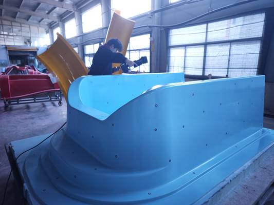
It allows a quality team to capture the full geometry of a wind turbine blade root or a composite aerospace fairing on-site, generating a dense point cloud for immediate analysis. While fixed CMMs remain the gold standard for baseline calibration, they cannot resolve the time-critical constraints of in-process inspection or field service. Portable solutions bridge this gap.
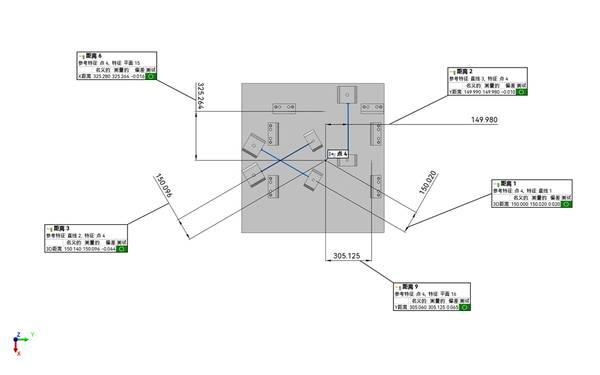
A device capable of handling large measurement volumes—for instance, scanning areas up to 2200×2200mm—while maintaining accuracy, turns the production floor into an inspection cell. The key is a system that supports robust global coordinate alignment and detailed deviation analysis, transforming a lab-bound dependency into a lean, responsive workflow.
Meeting Uncontrolled Environments with Certified Accuracy
A foundry floor is not a metrology lab. Temperature shifts, dust, and vibration are ever-present, yet the dimensional data for a complex sand casting must be irrefutable for downstream machining. Modern portable scanners have evolved to deliver repeatable, metrology-grade datasets under these conditions. INSVISION addresses this with hardware engineered for environmental resilience.
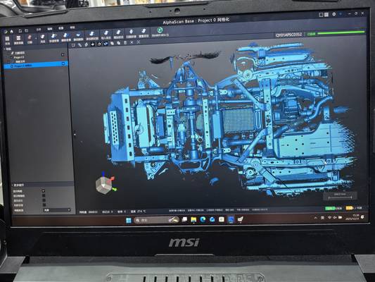
The INSVISION AlphaScan handheld scanner utilizes 50-line blue laser projection to penetrate dark surfaces and capture deep-hole structures common in castings.
For large-part modeling, where volumetric accuracy is paramount, the system employs a dual-camera setup with manual marker alignment, further stabilized by photogrammetry scale bars to establish a reliable global coordinate system independent of perfect lighting or fixed fixtures. This hardware capability is matched by PTB-certified software, where algorithms optimize point cloud registration and ensure data fidelity.
This combination allows for high-speed capture of intricate freeform surfaces on a rough casting, preserving dimensional integrity for reverse engineering or first-article inspection without the traditional scanning bottleneck.
Closing the Loop: From Scan Data to Corrective Action
The highest value of a 3d scanner for modeling is realized when it ceases to be a standalone measurement tool and becomes the core of a closed-loop quality system. The goal is to seamlessly close the gap between digital design (CAD) and physical reality. INSVISION’s ecosystem, pairing AlphaScan hardware with SMARTPARA Q software, is built for this integration.
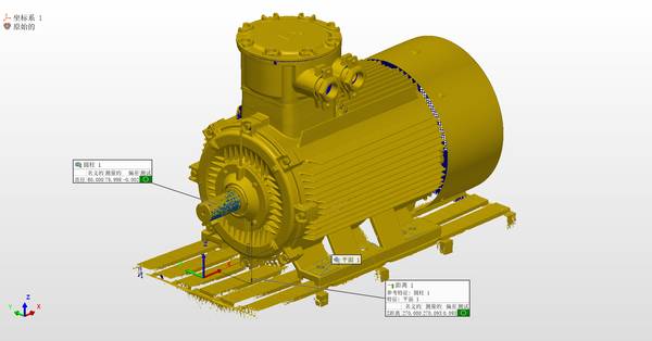
Scan data imports directly into inspection workflows, generating intuitive color deviation maps. These maps visually pinpoint wear patterns on a returned motorcycle engine cover or highlight dimensional drift in a batch of injection-molded housings. Built-in GD&T tools, aligned with ISO/ASME standards, automate tolerance analysis, while one-click reporting compresses compliance documentation from hours to minutes.
Crucially, PTB-certified software ensures scan outputs integrate with mainstream CAD formats (like SOLIDWORKS or CATIA) without translation errors, a critical requirement for both R&D prototyping and production quality tracking. The workflow becomes consistent: capture, compare, and correct.
Selecting a System for Complex Industrial Geometries
Choosing the right portable 3d scanner for modeling requires moving beyond generic specifications to a practical evaluation framework. Engineering and procurement teams should focus on four objective criteria tied directly to their use case:
- Measurement Volume and Adaptability: Can the system handle your largest typical part? Verify performance on highly curved surfaces and deep recesses.
- Surface Handling: Test the scanner on your specific materials—dark, matte castings, shiny composite surfaces, or reflective machined alloys—to ensure reliable data capture.
- Software Ecosystem: The software must not only process data but integrate with your existing PLM/ERP systems. Confirm seamless data export and the availability of automated reporting tools.
- Certification and Support: Ensure the system meets relevant international baselines (CE, FCC) and is backed by metrology-grade calibration certificates.
INSVISION positions its handheld systems, such as the AlphaVista series, for this multi-scenario industrial modeling. With specifications like cross-line blue lasers and high measurement rates, they are designed for complex geometries. Before procurement, validate the system on-site: check marker alignment stability on a curved composite panel and run a trial export to your quality management software.
The final decision should be grounded in your specific part materials, tolerance bands (for example, ±0.05 mm), production line rhythm, and reporting needs.
Determining Your Integration Path
The transition to portable 3D scanning is a strategic operational decision, not just a hardware purchase. To evaluate its fit for your lean production environment, start by defining the specific constraints you aim to solve. What is the largest part type you need to scan on-location—is it a fabricated weldment or a composite mold?
What are the surface conditions and critical tolerance bands for your first-article inspection reports? Finally, consider your production takt time: how must the inspection cycle align with it to prevent bottlenecks? By clarifying these parameters, you can map out a precise integration path that turns a portable scanner from a novel tool into a fundamental component of your quality workflow.
To get started, tell us about your part material, maximum part size, required tolerance bands, and current line takt time—we’ll help you determine if a portable 3d scanner for modeling fits your operational needs.
Hangzhou Insvision Technology Co.,Ltd.
Address: Building 1, No. 1399 Liangmu Road, Yuhang District, Hangzhou, Zhejiang 311121, China