
3d scanner resolution vs accuracy Selection Guide
In this articleWhy Visual Density Doesn't Guarantee Dimensional TruthMatching Your Scanner to Part Geometry and Tolerance ClassBridging the Divide with AI-...
This article cuts through the spec-sheet confusion, outlining how to match metrology hardware to real-world geometry and tolerance demands, ensuring your scan data supports QA sign-off without costly iteration.
Why Visual Density Doesn’t Guarantee Dimensional Truth
A high-resolution scan that fails ISO/ASME GD&T verification is merely expensive scrap data. Resolution defines a system’s ability to capture fine surface topology—essential for detecting micro-pitting on a bearing race or mapping wear distribution on a deep-black, machined coating. Accuracy, however, is the scanner’s certified, traceable deviation from true geometry.
It determines whether a drive motor base will mate correctly on an assembly line, regardless of how visually detailed the mesh appears. Prioritizing one over the other creates a critical gap: you might capture a surface texture perfectly but miss a structural deviation that causes an assembly failure weeks later.
The shop-floor need is for both—sufficient detail to see a defect and certified accuracy to measure it against the print.
Matching Your Scanner to Part Geometry and Tolerance Class
Selecting a device requires moving beyond stacked datasheet numbers to a practical assessment of the part and its tolerances.
- When Resolution Leads: Focus on applications where surface condition is paramount. This includes reverse engineering a complex mold cavity, documenting heritage components, or profiling surface finish on a composite panel. The key strength is model fidelity for analysis, not necessarily final inspection.
- When Accuracy is Non-Negotiable: This applies to any first-article inspection (FAI), tooling calibration, or GD&T verification for mating components. Here, the 0.02 mm tolerance band on a valve seat is the only metric that matters. A scanner lacking metrology-grade certification cannot close this loop.
Using separate instruments for these tasks is a bottleneck modern lean manufacturing cannot afford. The practical solution is a single system that aligns high resolution with metrology-grade accuracy, allowing an engineer to capture a narrow cooling-channel geometry and verify its positional tolerance in the same workflow.
Bridging the Divide with AI-Driven Metrology
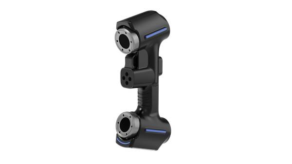
The debate between 3d scanner resolution vs accuracy is now being resolved on the shop floor through integrated hardware and software. The INSVISION AlphaScan exemplifies this shift, delivering a certified accuracy of ±0.02 mm while maintaining the high-resolution point clouds needed for detailed surface capture.
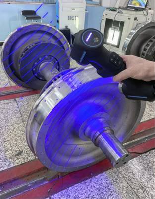
For engineers in harsh environments, its IP54 rating provides defense against coolant mist and grinding dust in a footprint 60% smaller than previous-generation systems.
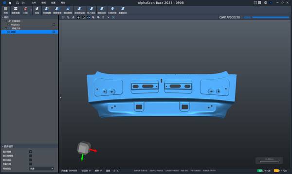
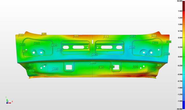
The workflow integration is critical. The system connects via Ethernet RJ-45 or USB 3.0 for direct MES connectivity. Its adaptive calibration algorithm improves measurement stability linearly with repeated use, supporting unattended operation. For a complex workpiece, data acquisition can be completed in approximately three minutes, enabling an operator to move swiftly from a handheld scan to a one-click color deviation map.
This directly replaces manual CMM dependency for freeform surfaces, keeping high-takt lines moving.
Validating the Workflow for Production Reliability
Implementing any new metrology tool requires validating its place in the inspection loop. Before deployment, engineers must cross-check the scanner’s calibration certificate against their internal standards and verify part-mounting stability for repeatability. Surface preparation for highly reflective or dark matte finishes should be confirmed to ensure first-pass success.
With an INSVISION system, the captured point cloud exports directly to professional inspection software (e.g., PolyWorks, GOM Inspect) for ISO-compliant reporting, embedding itself into Industry 4.0 traceability protocols. To prevent data bottlenecks, define your reporting cadence—shift-level summaries or per-batch reports—before going live.
The outcome is a streamlined process where a full geometric inspection of a pump housing takes minutes instead of hours, with errors on hidden structures highlighted instantly on a visual map.
Configuring Your Inspection Solution
The optimal workflow depends on your specific application. To evaluate fit, consider your primary part material, envelope size, required tolerance class, and existing reporting infrastructure.
INSVISION application engineers can then advise on boundary conditions, such as the system’s 0°C–50°C operational range for foundry or outdoor energy sites, and the necessary validation steps to ensure your scan data supports final QA sign-off without rework. Begin by outlining your current bottleneck: is it visualizing surface defects, or validating critical assembly tolerances?
Understanding where 3d scanner resolution vs accuracy fits in your quality workflow is the first step toward reliable production-line inspections.
Hangzhou Insvision Technology Co.,Ltd.
Address: Building 1, No. 1399 Liangmu Road, Yuhang District, Hangzhou, Zhejiang 311121, China