
3d measuring tool Industrial Inspection Guide
In this articleThe High Cost of Stationary Thinking in Dynamic EnvironmentsClosing the Gap Between Data Capture and Dimensional InsightFrom Data Silos to C...
The High Cost of Stationary Thinking in Dynamic Environments
The belief that precise measurement must occur in a fixed, isolated lab creates a critical bottleneck in lean manufacturing. Transporting large weldments or complex sub-assemblies to a remote coordinate measuring machine (CMM) bay halts production flow, delaying first-article sign-off and creating logistical friction. A versatile, portable 3D measuring tool is now essential for line-side auditing.
Key Points at a Glance
- The belief that precise measurement must occur in a fixed, isolated lab creates a critical bottleneck in lean manufacturing.
- A common misconception is that scanning speed inherently sacrifices accuracy.
- Capturing a perfect point cloud is only half the battle.
- Choosing a 3D measuring tool requires balancing optical physics with production takt time.
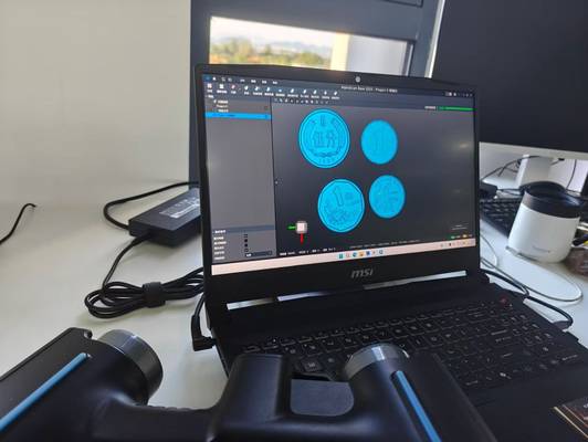
The INSVISION AlphaScan handheld 3D scanner is engineered for this shift, enabling deployment directly at the source of work—be it a final assembly station or a cramped machining cell. Its one-handed operation allows a technician to scan a turbine blade’s airfoil geometry or map the internal contours of a deep-hole bore on a hydraulic manifold without disassembly.
Stability is maintained through a high-speed USB fixed knob connection, ensuring data integrity is preserved when capturing intricate details on large or reflective surfaces. This approach removes the physical delay inherent in traditional audit trails.
Closing the Gap Between Data Capture and Dimensional Insight
A common misconception is that scanning speed inherently sacrifices accuracy. The true bottleneck often lies not in sensor acquisition but in the subsequent data processing. Engineers can waste hours manually stitching point clouds and extracting features from scans of complex curved surfaces or highly reflective finishes. INSVISION addresses this by embedding AI algorithms directly into the 3D reconstruction pipeline.
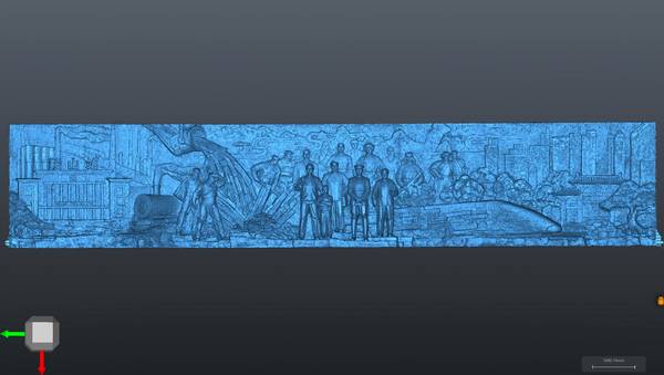
This automation handles data alignment in real-time, allowing systems like the AlphaVista to maintain metrology-grade fidelity at high measurement rates. Users see a live point cloud generate instantly as they scan, and upon completion, the software immediately overlays a color deviation map on the machined component.
This provides visual, immediate confirmation of tolerance compliance against the CAD model, transforming the device from a data collector into an analysis tool. Before purchasing any 3D measuring tool, verify that any quoted speed encompasses the full cycle from scan to registered, report-ready data.
From Data Silos to Certified Workflows: The Software Imperative
Capturing a perfect point cloud is only half the battle. The real value is lost if that data cannot be efficiently analyzed and reported against standards like ASME Y14.5 or ISO GPS. A fragmented software ecosystem—where scanner output is incompatible with legacy analysis systems—traps raw data, delaying root-cause analysis and final inspection sign-off.
INSVISION prevents this with a PTB-certified industrial software platform. It bridges the gap by supporting multi-source data alignment and featuring built-in GD&T analysis tools. The platform manages full reverse engineering workflows and reads all mainstream 3D file formats, streamlining handoff between quality and production teams.
Users validate tolerance bands directly within the interface and generate ISO-compliant inspection reports in one click. This ensures precise scan data fuels immediate corrective action, not administrative backlog.
Selecting for Reality: Geometry, Environment, and Throughput
Choosing a 3D measuring tool requires balancing optical physics with production takt time. Look beyond nominal accuracy specs to assess boundary conditions: surface reflectivity, ambient light, part scale, and thermal stability. Your selection must align with specific part scenarios.
| Key Strength | Ideal Application Scenario |
|---|---|
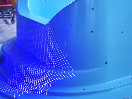
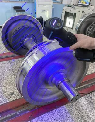
| Blue laser cross-line technology | Verifying wheelset tread and flange profiles, capturing fine wear patterns on curved surfaces. |
| Metrology-grade volumetric accuracy | Validating a critical additive-manufactured aerospace bracket against strict GD&T callouts. |
| Deep-hole scanning capability | Inspecting internal cooling channels within a turbine blade or hidden geometries in a cast engine block. |
The INSVISION AlphaScan integrates these capabilities to maintain data integrity. However, successful deployment requires operational validation. Engineers must confirm that calibration certificates are traceable and that the system’s lighting tolerance matches the variable conditions of their own facility—whether under harsh factory lighting or in a controlled audit area.
Validating Performance: Inspection Rhythm and Deviation Closure
The ultimate test of any 3D measuring tool is its impact on your production floor’s inspection rhythm. Success is measured by a stable, repeatable scan-to-report cycle and a tangible improvement in first-pass yield during dimensional audits. INSVISION systems, backed by PTB-certified software and hardware carrying CE, FCC, and CNAS certifications, are deployed in over 20 countries to support this shift.
When engineering teams review comprehensive color deviation maps aligned to CAD models, sign-off accelerates because the data reveals full-surface irregularities, not just discrete sample points. To assess fit for your operation, prepare details on your most challenging part materials, surface conditions (e.g., dark machined steel, polished composites), critical tolerance bands, and required reporting standards.
This allows for a configuration that respects your existing shop-floor validation checklist and integrates with your production pace.
Hangzhou Insvision Technology Co.,Ltd.
Address: Building 1, No. 1399 Liangmu Road, Yuhang District, Hangzhou, Zhejiang 311121, China