
3D Laser Profilers: A Technical Guide for Industrial Metrology
At its core, a 3D laser profiler functions on the principle of optical triangulation. The system projects a precise laser line onto a target object.
The Operating Principle: From Laser Line to 3D Data
At its core, a 3D laser profiler functions on the principle of optical triangulation. The system projects a precise laser line onto a target object. One or more high-resolution sensors, positioned at a known angle to the laser source, capture this line. As the line encounters surface contours, it deforms.
Common Questions
What should teams check when evaluating The Operating Principle: From Laser Line to 3D Data?
At its core, a 3D laser profiler functions on the principle of optical triangulation.
What should teams check when evaluating Decoding Critical Technical Specifications?
Selecting a 3D laser profiler requires a clear understanding of key specifications and how they impact real-world performance.
What should teams check when evaluating Industrial Applications: Beyond Basic Measurement?
In-Line Quality Control & First-Article Inspection: This is the primary application.
This process generates a single cross-sectional profile. To build a complete 3D model, either the profiler moves relative to the object, or the object moves under a fixed profiler. The system captures thousands of these profiles per second, assembling them into a comprehensive point cloud.
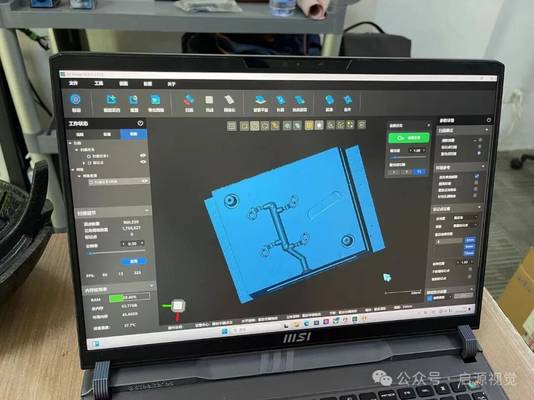
Advanced software algorithms then process this raw data, stitching profiles, filtering noise, and compensating for environmental factors to produce a metrology-grade digital twin. Modern systems, like the INSVISION AlphaScan handheld scanner, integrate AI-driven processing to enhance feature recognition and significantly reduce the data artifacts common in complex scanning environments.
Decoding Critical Technical Specifications
Selecting a 3D laser profiler requires a clear understanding of key specifications and how they impact real-world performance.
- Accuracy and Resolution: These are distinct but related. Accuracy refers to how close a measurement is to the true value, often stated as a volumetric figure (e.g., ±0.1 mm). Resolution defines the smallest detectable surface detail. For general manufacturing, an accuracy of 0.25 mm may suffice, while aerospace or precision tooling often demands sub-0.1 mm capabilities.
- Scan Rate: Measured in points or measurements per second (e.g., 7.1 million measurements/sec for the INSVISION AlphaVista), this dictates throughput. A high scan rate enables rapid inspection of large or complex parts directly on the production line, making 100% inspection feasible where previously only sampling was possible.
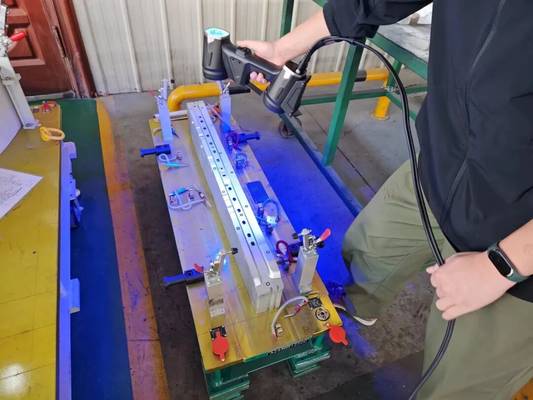
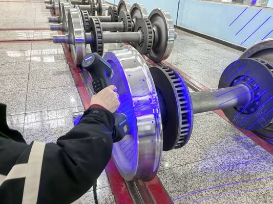
- Laser Wavelength: This influences material compatibility. Blue lasers (e.g., 520nm, as used in INSVISION systems) offer superior performance on reflective, shiny, or semi-transparent surfaces that typically scatter red laser light, causing measurement dropouts. Laser safety class (e.g., Class 3R) is also a critical factor for operator protection in open factory settings.
- Environmental Robustness: Industrial equipment must survive the shop floor. Specifications for operating temperature (e.g., -5°C to 40°C), ingress protection (IP rating), and vibration tolerance determine if a system is suitable for a metrology lab or a busy assembly station.
Industrial Applications: Beyond Basic Measurement
In-Line Quality Control & First-Article Inspection: This is the primary application. Profilers instantly compare scanned parts against their nominal CAD models, generating intuitive color-coded deviation maps. Areas within tolerance are green, while undersized and oversized regions appear in blue and red, respectively.
This allows for immediate visual identification of tooling wear, spring-back, or assembly issues, feeding data directly into Statistical Process Control (SPC) systems for Industry 4.0 analytics.
Digital Reverse Engineering: For legacy parts without CAD data or for competitive analysis, 3D profilers capture complete surface geometry non-destructively. The resulting data can be exported as mesh files (STL, PLY) or, with advanced software, converted into parametric CAD models (STEP, IGES) for redesign, tooling creation, or digital archiving.
Large-Volume Metrology: Inspecting aircraft panels, wind turbine blades, or large molds requires specialized profilers with extended measurement volumes. Systems like the INSVISION AlphaVista series are engineered for this, with specifications that account for realistic error accumulation over distance (e.g., 0.1 mm + 0.015 mm/m).
The handheld form factor is key here, bringing the measurement to the part—often eliminating the cost and disruption of moving massive components to a CMM.
Selecting a System: A Criteria-Based Approach
Choosing the right 3D laser profiler is an exercise in matching capability to requirement.
- Define the Application Fit: Start with the workpiece: typical size, material, surface finish, and required tolerance. A portable handheld system prioritizes flexibility for diverse, on-location tasks. A fixed-mount or robotic system delivers maximum speed and repeatability for high-volume, dedicated inspection cells.
- Evaluate the Software Ecosystem: The hardware is only half the solution. The software must integrate seamlessly into existing workflows. Look for capabilities like direct CAD comparison, automated Geometric Dimensioning and Tolerancing (GD&T) analysis, and customizable reporting. Software with AI-assisted alignment and cleanup, such as INSVISION suite, can reduce operator dependency and ensure consistency.
- Validate with Real-World Trials: Always test with your own parts. Vendor demo scans on ideal samples can be misleading. Provide samples that represent your challenges: deep pockets, sharp edges, mixed materials, and highly reflective surfaces. This reveals true system performance and software usability.
- Consider Total Cost of Ownership: Factor in calibration services, technical support availability in your region, training requirements, and software licensing. A system that degrades without proper support or requires expert operators may have a high hidden cost, regardless of its purchase price.
For engineers and quality managers, the value of a 3D laser profiler is measured in reduced scrap, faster time-to-market, and robust, data-driven process control. By focusing on core principles and application-specific criteria, you can implement a system that delivers tangible ROI on the factory floor.
Hangzhou Insvision Technology Co., Ltd.
Address: Building 1, No. 1399 Liangmu Road, Yuhang District, Hangzhou, Zhejiang 311121, China