

When Large Parts Demand Precision: 3D Scanning for Heavy Castings, Tooling and Assemblies
Large workpieces don’t forgive mistakes. A single casting that weighs several tons, a wind turbine hub spread across two meters, a thermoforming mold that needs
Where the Difficulty Actually Lives: Size, Surface and Stability
The first thing that separates large workpieces from desktop-sized parts isn’t the volume — it’s the accumulation of small error sources that scale with the object. A sand-cast pump housing may arrive with a dark, matte surface that absorbs laser light unevenly. A machined steel die can have mirror-like finishes that send a blue laser into saturation.
Deep pockets, internal ribs, and narrow flange gaps create shadow zones that a fixed scanner will never see. On top of that, the part itself can move. A large weldment resting on three-point supports may relax differently between morning and afternoon, and a floor-transmitted vibration from a nearby overhead crane is enough to disturb a measurement that relies on a rigid reference frame.
Deployment Validation Checklist
| Focus Area | Decision Point | Deployment Note |
|---|---|---|
| Target part | Check size, surface condition, and key tolerances against the scan task | Run a full trial scan on a representative part |
| Data workflow | Verify point cloud, deviation map, and quality-report handoff | Confirm export formats and review ownership in advance |
| Shop-floor use | Review training, calibration, lighting, and working space | Keep the validation record as a repeatable inspection reference |
Key Points at a Glance
- The first thing that separates large workpieces from desktop-sized parts isn’t the volume — it’s the accumulation of small error sources that sc…
- A practical approach to large-part scanning begins with understanding which features matter for downstream function.
- Raw data on a large workpiece is intimidating.
- When a shop starts scanning parts that are measured in meters rather than centimeters, the bottleneck shifts from scanner resolution to workflow…
Size also forces a decision about how to register scans. When an object exceeds a meter or two, sticking reference targets on every surface and hoping they stay put becomes a poor strategy. The targets can shift under temperature changes, get knocked off during handling, or simply run out in areas where the part geometry offers no natural landing spot.
Dimensional tolerances for large workpieces are often tighter than they look, too. A 2,500 mm long frame may carry a flatness callout of 0.3 mm, which means the scanning system must hold its own volumetric accuracy across the full envelope while coping with all the surface variability described above.
Scanning Strategy for Massive Parts: No Blind Spots, No Drift
A practical approach to large-part scanning begins with understanding which features matter for downstream function. It’s rarely necessary to capture every square millimeter at the same resolution. Mating surfaces, bolt-hole patterns, and seal grooves call for dense point spacing; cosmetic surfaces and large clearance areas can be scanned at a coarser pitch.
This graded-resolution strategy saves processing time and keeps file sizes manageable without sacrificing inspection coverage.
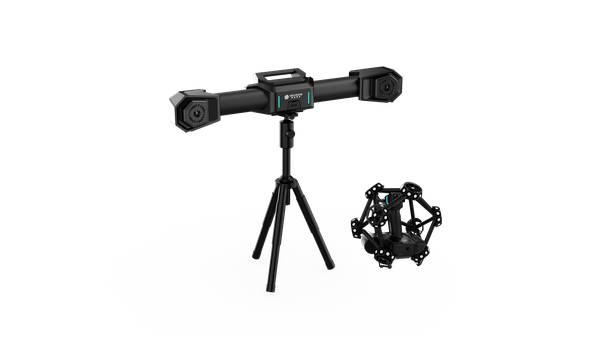
The INSVISION X-Track wireless optical tracking system changes how the operator handles part movement. The tracker watches the scanner’s position in real time, so the part itself doesn’t need to be peppered with targets. The scanner can be moved freely around the part, and the coordinate system stays locked to the tracker’s reference, not to the part.
This is especially useful for large castings that are still sitting on the foundry floor or for tooling that’s too heavy to lift onto a granite table. The AlphaScan handheld scanner, running a blue laser line, supplies the measurement density.
On a dark, slightly oxidized cast iron surface, the blue wavelength still returns a clean profile, and the scanner’s exposure control can be adjusted per patch to handle mixed-material assemblies where a painted area sits next to a raw machined pad.
Deep cavities and narrow slots remain the toughest geometry. The handheld form factor helps because the operator can angle the scanner into a pocket, but the critical step is verifying that the collected data actually reaches the bottom of the feature. A quick on-site preview of the point cloud — shaded by normal deviation — tells the operator where the scan is thin.
Those areas can be re-scanned immediately, before the equipment is packed up and the part ships.
From Point Cloud to a Report That Means Something
Raw data on a large workpiece is intimidating. The point cloud can easily run into tens of millions of points, and without a clear workflow the file becomes a digital paperweight. The first post-processing step is alignment. For parts that have a defined datum reference frame, the scan data needs to be aligned to that frame, not just to itself.
The INSVISION 3D software environment supports alignment to engineered datums, which is essential when the inspection report must match the drawing’s tolerance scheme.
Once aligned, the dataset moves into comparison against CAD. On a large part, a simple color map isn’t always enough. The areas of interest need to be segmented so that surface profile deviations, hole positions, and local flatness are reported separately.
A global pass/fail on a 2-meter stamping die isn’t actionable — the shop needs to know that the trim edge is within 0.1 mm, the draw beads are slightly high, and the rest area is within tolerance. The software’s ability to isolate regions and apply GD&T annotations directly on the scan data turns a colorful picture into a machinable instruction.
The final report, often a PDF with embedded views and deviation tables, becomes part of the quality record. For first-article inspection of a large mold, the report might travel to the customer’s engineering team for approval. The repeatability of the scanning setup matters here: if the same part were scanned again a week later, the report should show the same callouts within the measurement uncertainty.
That consistency depends on the tracking system’s stability and on the operator’s discipline in following the same scan sequence and alignment procedure.
Choosing a System That Won’t Limit the Part Size
When a shop starts scanning parts that are measured in meters rather than centimeters, the bottleneck shifts from scanner resolution to workflow practicality. The first question is whether the tracking system can handle the entire volume without requiring the operator to stop and relocate reference points.
The X-Track system’s wireless design removes the tether between scanner and tracker, which means the operator can walk around a large assembly without managing cables. The second question is about scanning speed and data handling.
The AlphaScan’s measurement rate keeps scan passes short, but the real efficiency gain comes from the ability to preview data on the fly, so the operator never leaves the site with a low-quality dataset.
Surface preparation is often the hidden cost. Large parts frequently arrive with mill scale, oil, or dust. A blue laser scanner can often scan light surface contamination, but heavy oil that pools in pockets will still cause problems. As a rule of thumb, if the surface can be wiped clean with a rag, it’s probably scannable.
Heavily reflective machined surfaces may need a thin coat of developer spray, but the decision should be made after a quick test scan on the actual material, not assumed from a datasheet.
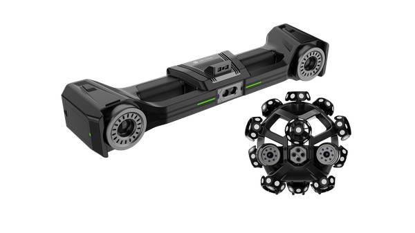
Large workpieces will always be physically demanding to measure, but the right 3D scanning setup can turn a multi-day inspection job into a same-day task.
The combination of a handheld blue laser scanner like AlphaScan and an optical tracking system like X-Track gives shops a way to capture complete geometry without moving the part, without covering it in targets, and without losing the datum reference that ties the scan back to the drawing. For foundries, mold builders, and heavy fabricators, that’s a direct path to tighter process control and fewer late-stage rework surprises.
Hangzhou Insvision Technology Co.,Ltd.
Address: Building 1, No. 1399 Liangmu Road, Yuhang District, Hangzhou, Zhejiang 311121, China