

When Castings, Composites, and Deep Cavities Define True 3D Scanner Accuracy
The moment a quality engineer needs to verify a sand-cast pump housing or a thin-walled composite intake, the phrase “3D scanner accuracy” stops being a spec sh
The Object Sets the Accuracy Baseline, Not the Scanner
Accuracy in industrial 3D scanning is never a property of the scanner alone. It is a system result that includes the part, the environment, the operator, and the post-processing chain. A matte, rigid, medium-sized metal part with open geometries will scan easily. A dark, glossy plastic housing with deep ribs, tall bosses, and a 0.2 mm wall thickness will challenge even a well-calibrated system.
The laser wavelength, exposure time, and standoff distance that work for one material can fail for another. For instance, many blue laser scanners excel on reflective metals because the shorter wavelength reduces speckle noise and improves edge definition.
That same blue laser may struggle on a translucent polymer if the material scatters the beam below the surface, creating a fuzzy point cloud that undermines the nominal accuracy.
Deployment Validation Checklist
| Focus Area | Decision Point | Deployment Note |
|---|---|---|
| Target part | Check size, surface condition, and key tolerances against the scan task | Run a full trial scan on a representative part |
| Data workflow | Verify point cloud, deviation map, and quality-report handoff | Confirm export formats and review ownership in advance |
| Shop-floor use | Review training, calibration, lighting, and working space | Keep the validation record as a repeatable inspection reference |
Practical Workflow
- The Object Sets the Accuracy Baseline, Not the Scanner — Accuracy in industrial 3D scanning is never a property of the scanner alone.
- Part Geometry Traps That Break Measurement Consistency — Beyond surface and material, the geometry of the object introduces error sources that are often overlooked during scanner selecti…
- Designing a Scan Strategy Around the Object, Not the Devi… — A practical approach starts with an object profile: material class, surface condition, approximate dimensions, wall thickness, cr…
- Verification, Reporting, and the Repeatability Loop — Once the scan data is aligned, the inspection workflow moves to a CAD comparison map.
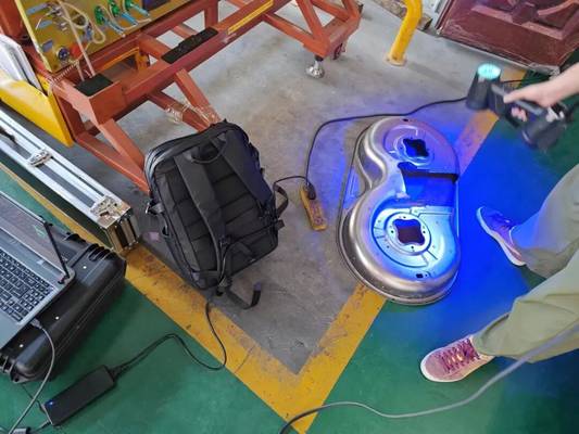
INSVISION’s AlphaScan handheld 3D scanner operates with a 520 nm blue laser and uses AI-driven exposure control to adapt to varying surface conditions in real time. Instead of forcing the operator to manually adjust parameters for each material, the system modulates laser power and camera gain on the fly.
This matters because a typical inspection workflow for a machined bracket, a raw casting, and a carbon-fiber laminate might move through three different surface behaviors in a single shift. The scanner’s volumetric accuracy of 0.1 mm ± 0.015 mm/m is a meaningful reference only when the object’s surface is properly managed.
Without adaptive exposure, dark or reflective surfaces can produce systematic errors that far exceed the device’s quoted accuracy band.
Part Geometry Traps That Break Measurement Consistency
Beyond surface and material, the geometry of the object introduces error sources that are often overlooked during scanner selection. Deep blind holes, narrow slots, internal ribs, thin edges, and sharp corners all create data voids or misregistration artifacts. When a scanner cannot return a signal from the bottom of a 50 mm deep bore, the software interpolates or leaves a hole.
That interpolation can fake a sense of completeness while hiding the fact that the measured depth is off by several tenths of a millimeter. Likewise, thin edges become unreliable when the laser spot is comparable to the edge radius; the point cloud smears, and the resulting mesh rounds off what should be a sharp feature.
Parts that are prone to vibration or deformation during scanning add another layer of complexity. A large sheet-metal weldment might sag under its own weight if not supported, moving the surface by a few hundred microns between the start and end of a scan. A warm casting fresh from a machining cell will contract as it cools, and the scanner will capture a transient shape rather than the final geometry.
In these cases, the scanning strategy must account for clamping, thermal soak, and the sequence of data capture. The AlphaScan, with its lightweight handheld form factor, allows the operator to move around the part rather than repositioning the part itself. This reduces the risk of introducing new deformation during measurement and helps preserve the chain of accuracy from object to digital twin.
Designing a Scan Strategy Around the Object, Not the Device
A practical approach starts with an object profile: material class, surface condition, approximate dimensions, wall thickness, critical features, and the environmental state on the floor. For a cast aluminum gearbox housing, the profile might read: mid-gray, slightly rough as-cast surface, 400 mm × 300 mm × 200 mm envelope, numerous oil galleries and dowel holes, temperature 28°C.
The inspection goal is a full-field CAD comparison with a tolerance band of ±0.15 mm on machined datums and ±0.5 mm on cast surfaces.
From this profile, the scan strategy is built backward. The operator first defines the datums that will control alignment: machined flange faces and two dowel holes. The scanning path is planned to capture these reference features at high resolution before moving to the cast bodies. Marker placement is adjusted so that the scanner can lock onto the same reference frame even when the part is partially obscured by fixturing.
During the scan, the AlphaScan’s real-time preview shows point density and missing areas, so the operator can make a second pass on the deep oil galleries where the initial scan left gaps. The key is not to scan everything at maximum resolution; instead, resolution is varied based on feature criticality.
After capture, the raw point cloud is cleaned and aligned in INSVISION’s 3D software, where the measured datums are used to register the scan data to the nominal CAD model.
Verification, Reporting, and the Repeatability Loop
Once the scan data is aligned, the inspection workflow moves to a CAD comparison map. The software computes surface deviations across the entire part, with color-coded analysis that highlights areas outside the tolerance bands. For the gearbox housing, the machined mounting surfaces should show deviations within ±0.1 mm, while the cast walls may vary more but should not exceed the casting allowance.
The built-in GD&T tools in the SMARPARA Q module allow the engineer to pull flatness, parallelism, and position checks directly from the scanned data, reducing the need to run separate CMM programs for every characteristic.
The final step that often gets neglected is the repeatability verification. A single scan of a single part is not a process. The engineer should scan the same part three times, with the part removed and re-fixtured between scans, and compare the results.
Variation in the measured datums or in critical feature dimensions will reveal how much of the total measurement uncertainty comes from the object, the fixturing, and the operator. The AlphaScan’s positioning accuracy of 0.25 mm and its volumetric accuracy framework provide a known baseline; the repeatability study then shows whether the object’s own characteristics are introducing extra scatter.
If the same cast housing shows a 0.3 mm shift in a dowel position across three scans, the problem is likely a clamping issue or thermal drift, not the scanner.
A genuine accuracy conversation does not end with a device specification. It ends with a documented scanning procedure that links the object’s material, surface, geometry, and thermal state to a repeatable measurement outcome.
The INSVISION AlphaScan handheld scanner, combined with object-aware scan planning and the verification tools in the 3D INSVISION software, makes it possible to bring that level of rigor out of the lab and onto the production floor. The real value of 3D scanner accuracy shows up when the same part, scanned by different operators on different shifts, delivers the same deviation map and the same pass/fail call.
Hangzhou Insvision Technology Co.,Ltd.
Address: Building 1, No. 1399 Liangmu Road, Yuhang District, Hangzhou, Zhejiang 311121, China