

Why Blade Surface Geometry Defeats Conventional Inspection Tools
A turbine blade, a compressor airfoil, or an impeller vane shares one trait that makes dimensional verification uniquely difficult: the surface is never a simpl
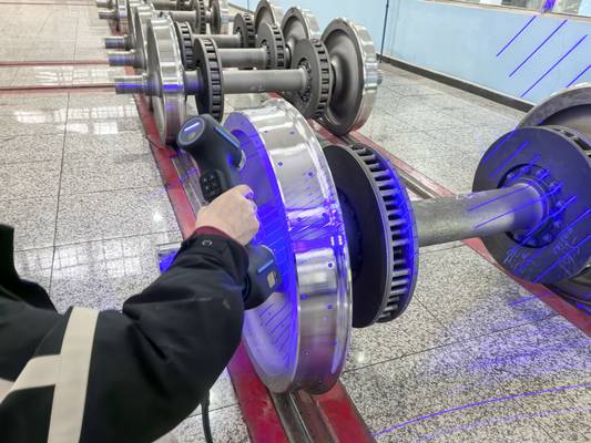
The real difficulty with blade surfaces is not just the freeform shape. A single blade can present a dozen different inspection conditions within a few centimeters of scan distance. The suction side may be matte and diffusely reflective, while the pressure side near the root fillet picks up shop oil and becomes semi-specular.
The leading edge radius can be under 0.3 millimeters, requiring dense point spacing to resolve the true profile rather than a smoothed approximation. Trailing edge thickness tapers toward zero, and the root platform often includes dovetail serrations, seal slots, and cooling holes that create occluded pockets.
Deployment Validation Checklist
| Focus Area | Decision Point | Deployment Note |
|---|---|---|
| Target part | Check size, surface condition, and key tolerances against the scan task | Run a full trial scan on a representative part |
| Data workflow | Verify point cloud, deviation map, and quality-report handoff | Confirm export formats and review ownership in advance |
| Shop-floor use | Review training, calibration, lighting, and working space | Keep the validation record as a repeatable inspection reference |
In a repair or incoming inspection scenario, the blade arrives with no fixture reference, no defined alignment datums, and possibly a coating whose thickness needs to be evaluated against the underlying substrate.
Traditional contact methods struggle with every one of those conditions simultaneously, and the result is either an inspection report that averages out the most critical local deviations, or a measurement routine so slow that sampling becomes the bottleneck in the quality loop.
## Object Portrait: What Makes a Blade Surface Hard to Digitize
Blade surfaces combine four material and geometric factors that interact in ways most inspection plans underestimate. The first is curvature variation: the chordwise profile changes from a broad, gently curved mid-chord region to a tightly arcing leading edge, and the spanwise twist adds a second axis of curvature that means a single cross-section template cannot represent the full surface.
The second factor is surface condition. As-cast blades may have a slight texture that aids laser return, but coated or service-run blades can exhibit a range from low-reflectivity ceramic finishes to mirror-like polished sections that challenge laser-based scanners. The third factor is edge acuity.
The transition from the pressure side to the suction side around the leading edge is not a sharp crease but a continuous blend, and capturing that blend accurately requires scan data that wraps around the edge without a gap or a stitch error.
The fourth factor is access: the root platform, under-platform area, and shroud interlock features create narrow cavities where a scanner must maintain a short standoff distance while still collecting valid data.
When these four factors compound, the inspection data can degrade in predictable ways. A scanner that works well on the mid-span may lose track on the leading edge, forcing the operator to reacquire alignment and introducing a registration error that propagates through the rest of the scan.
A scanner that cannot handle the semi-gloss surface of a coated blade will produce range noise that masks small but out-of-tolerance deviations, such as a 0.05 millimeter erosion pocket on the pressure side.
INSVISION addresses these failure modes with the AlphaScan through a combination of blue laser projection, which is less sensitive to ambient light and surface reflectivity than red laser alternatives, and a software processing pipeline that evaluates point confidence per patch rather than applying a global smoothing filter.
The result is that the scanner tells the operator where the data is reliable and where it is thin, rather than silently filling gaps with interpolated geometry.
## Scanning Strategy: Building a Repeatable Data Acquisition Routine
A blade inspection routine with the AlphaScan typically starts with temporary reference targets placed on the fixture or on a non-critical area of the blade platform, not on the airfoil surface itself. This avoids masking the very surface being inspected. The scanner tracks these targets to maintain a global coordinate frame, so the operator can move around the blade, flip it, or reposition it without losing alignment.
The scanning path follows a deliberate sequence: suction side mid-span first to establish a stable base cloud, then the leading edge with a rolling motion that keeps the scanner roughly normal to the surface, then the pressure side with attention to the root fillet where the curvature tightens.
The trailing edge is acquired last, often with the scanner angled slightly to capture both the pressure and suction side flanks in overlapping passes.
For blades with cooling holes or film-cooling arrays, the scan density is increased around each hole perimeter. The AlphaScan software allows the operator to define a region of interest after the initial scan and prompt a re-scan of that zone at a closer standoff, effectively increasing the local point density without extending the overall scan time.
The raw point cloud is then cleaned of outliers, and the software aligns it to the nominal CAD model using a best-fit routine that can be weighted to specific datum features. The core deliverable at this stage is a color-mapped deviation plot that shows where the as-built or as-used surface deviates from the design intent.
The engineer can read the leading edge thickness, the chord length, the maximum camber deviation, and the surface profile tolerance all from the same dataset, without running separate probing routines for each parameter.
## Data Workflow: From Point Cloud to Actionable Report
Once the scan data is aligned, the inspection workflow inside the INSVISION software environment follows a structured sequence that can be saved as a template and reused for subsequent blades of the same part number. The first step is a surface comparison against the nominal CAD model, with the tolerance band set to the engineering specification.
The second step is a geometric dimensioning and tolerancing evaluation on specific callouts: profile of a surface, position of cooling holes, and local thickness at defined spanwise sections. The software extracts these values from the scan data itself, without requiring the operator to manually pick points.
The third step is a report generation that includes the color map, the GD&T results, and a pass/fail summary tied to the part serial number.
For blades that are part of a service inspection program, the data from the current inspection can be overlaid with historical data from the same serial number. This trend analysis shows whether a specific blade is eroding at a predictable rate, whether the coating is thinning uniformly, or whether a local deformation is progressing.
The AlphaScan system supports this through a registration routine that aligns the current scan to the previous scan rather than to the nominal CAD, effectively isolating the change between inspection intervals. The output is not just a dimensional report but a degradation map that can inform maintenance planning and remaining-life estimates.
## Where the Approach Fits and Where It Hits Its Limits
The AlphaScan handheld scanner is not a universal solution for every blade inspection scenario. If the blade is smaller than roughly 20 millimeters in chord length, the scanner’s minimum standoff and field of view may make data collection less efficient than a structured light system with a smaller measurement volume.
If the blade is still mounted in the engine and the inspection requires access through a borescope port, the handheld form factor cannot reach the surface. In those cases, the AlphaScan is better suited to the bench inspection workflow where the blade is removed and can be fixtured or held in a shop environment. What the system does well is compress the gap between the metrology lab and the production floor.
It delivers a level of surface detail that would be impractical to collect with a touch probe, and it does so without requiring the blade to be moved to a temperature-controlled room, mounted on a granite table, and aligned by a metrology specialist.
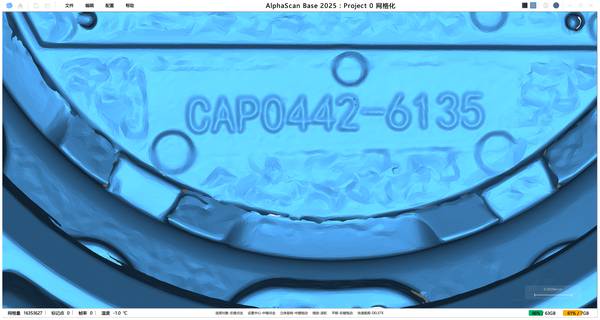
The practical takeaway for manufacturers and overhaul shops is that blade surface inspection should be designed around the object, not around the instrument. The instrument serves the blade geometry, surface condition, and inspection tolerance. When the workflow starts with the blade’s physical characteristics and works backward to the scanning strategy, the data becomes a reliable basis for engineering decisions.
When the workflow starts with the tool and forces the blade to fit its constraints, the data degrades. INSVISION positions the AlphaScan within that object-first philosophy, giving the operator control over scan density, alignment strategy, and report content so that the inspection output matches the engineering requirement rather than the scanner’s default setting.
Hangzhou Insvision Technology Co.,Ltd.
Address: Building 1, No. 1399 Liangmu Road, Yuhang District, Hangzhou, Zhejiang 311121, China