

Getting Weld Seam Inspection Right: The Geometry Problem That Gauges Miss
A weld seam rarely behaves like a CAD model. The surface wanders from convex to concave, the toe blends into the parent metal with no sharp edge to measure, and
The object itself dictates the approach. A fillet weld on a mild steel bracket is dark, slightly textured, and rigid enough to hold its shape. A butt weld on a thin stainless vessel, by contrast, may reflect overhead lights like a mirror and distort under clamping pressure. INSVISION has built its hardware and software stack around these material realities rather than treating every surface as an ideal diffuse target.
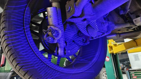
The AlphaScan handheld 3D scanner uses blue laser projection that registers on modestly reflective and dark surfaces without requiring spray coating in most cases, which matters when the part is a welded assembly destined for a cleanroom or a food-grade enclosure where developer residue is unacceptable.
Deployment Validation Checklist
| Focus Area | Decision Point | Deployment Note |
|---|---|---|
| Target part | Check size, surface condition, and key tolerances against the scan task | Run a full trial scan on a representative part |
| Data workflow | Verify point cloud, deviation map, and quality-report handoff | Confirm export formats and review ownership in advance |
| Shop-floor use | Review training, calibration, lighting, and working space | Keep the validation record as a repeatable inspection reference |
The handheld form also means the user can walk around a large fabrication, capture the weld cap and root side where accessible, and fill gaps in the data by revisiting a feature from a different angle without repositioning the entire workpiece.
Mapping the Weld Crown and Transition Zone
The common failure mode in weld inspection is not missing a gross defect; it is missing the gradual transition. A fatigue crack starts where the toe radius is inconsistent, and a corrosion cell forms in a slight undercut that a visual inspector might dismiss as marginal. Traditional profilometry captures a single cross-section every few inches, leaving the space between profiles unmeasured.
With the AlphaScan, the operator sweeps the scanner along the length of the joint, and the software reconstructs a continuous point cloud that resolves the crown shape, toe radius, and the heat-affected zone on both sides of the bead.
Scenario Snapshot
A practical way to read the article is through this scenario:
- Mapping the Weld Crown and Transition Zone: The common failure mode in weld inspection is not missing a gross defect;
- Working with Reflective, Thin, and Distortion-Prone…: Stainless steel and aluminum welds create two simultaneous problems: high reflectivity and a tendency to move duri…
- From Point Cloud to Pass/Fail Decision in the Produ…: The metrology chain after scanning needs to be fast enough to keep up with the welding cell.
The data density matters because weld geometry is rarely uniform. On a circumferential pipe weld, the overhead position tends to droop slightly compared to the flat position, creating a gradual change in reinforcement height. A single-profile gauge might catch the start and end of that droop but miss the exact point where the geometry falls out of tolerance.
The 3D scan builds a full surface, so the alignment software can generate a deviation map that shows the reinforcement height as a color gradient along the entire circumference. The quality engineer immediately sees whether the deviation is localized or progressive, and that visual summary often replaces a page of handwritten gauge readings.
Working with Reflective, Thin, and Distortion-Prone Parts
Stainless steel and aluminum welds create two simultaneous problems: high reflectivity and a tendency to move during scanning. A thin-walled aluminum manifold with a circumferential weld may relax slightly when unclamped, and the scanner must capture the as-built shape without assuming the part is rigid.
INSVISION addresses the reflectivity challenge through the blue laser wavelength and dynamic exposure control built into the AlphaScan, which adjusts acquisition parameters on the fly as the stripe passes from a brushed parent metal into a polished bead. The operator does not need to stop and dial in settings for each zone.
Distortion is a measurement target, not a nuisance. When a multi-pass weld shrinks and pulls a plate out of flatness, the inspection task is to quantify that distortion and compare it to the allowable envelope. The scanner captures the entire welded assembly in its free state, and the software overlays the nominal CAD model.
The resulting deviation map shows not just the weld geometry but the global deformation pattern, which is valuable feedback for the welding engineer adjusting the sequence or heat input. The same scan data can be sectioned to measure throat thickness, leg length, and face width at any location without re-scanning the part.
From Point Cloud to Pass/Fail Decision in the Production Flow
The metrology chain after scanning needs to be fast enough to keep up with the welding cell. A typical workflow starts with the operator connecting the AlphaScan to a laptop running INSVISION’s inspection software. The scan data is aligned to the CAD model—either a best-fit alignment for general weld geometry or a datum-based alignment when the inspection must reference specific machined surfaces.
The software extracts the weld cross-sections at user-defined intervals, computes the standard weld parameters, and flags any value that falls outside the tolerance band.
The output is a report that combines a color map of the full weld with tabulated section measurements. For a batch of welded brackets, the inspector can set up a template once and then apply it to every subsequent scan, so the fifth part of the shift is evaluated against the same criteria as the first.
Historical data stays available for trend analysis, which is useful when a process drifts and the team needs to correlate a change in leg length with a specific shift or filler lot. The report format is configurable; some shops want a simple pass/fail summary while others need the full deviation map for customer documentation.
Building a Repeatable Inspection Protocol That Scales
The value of a 3D scanning system is not fully realized until the protocol is written down and repeatable. A weld inspection protocol should specify the scan coverage, the number of sections, the alignment method, the tolerance set, and the sampling frequency for production runs.
The AlphaScan’s mobility allows the user to define a scan path that covers the joint and the adjacent parent metal without requiring the part to be moved to a dedicated metrology lab. For large weldments, the operator can scan in sections, and the software stitches the point clouds into a single dataset.
Where the process becomes self-correcting is in the feedback loop. When a weld falls outside tolerance, the deviation map points to the exact location and quantifies the error in three dimensions. The welder or robot programmer can adjust the parameters and re-scan the next part to verify the correction. Over time, the organization builds a library of scan data that correlates weld parameters with geometric outcomes.
That library is a practical asset when introducing a new weld procedure or qualifying a new batch of filler metal. The AlphaScan does not eliminate the need for weld process knowledge, but it gives the team a measurement tool that captures the full story of the joint, not just the few points where a gauge happened to be placed.
Hangzhou Insvision Technology Co., Ltd.
Address: Building 1, No. 1399 Liangmu Road, Yuhang District, Hangzhou, Zhejiang 311121, China