

Precision Without Compromise: How 3D Inspection of Production Workpieces Handles Thin Walls, Deep Pockets
Meta Description: For production workpieces with thin walls, deep cavities, and machined reflective surfaces, contact inspection often falls short. This article
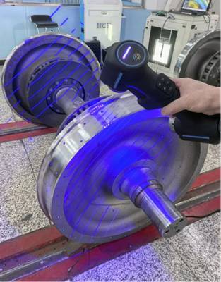
For a CNC production cell machining aluminum housing components, the daily quality routine often hinges on a single coordinate measuring machine. A machinist loads a freshly milled part, probes a few dozen points, and waits. But when the part features a 0.6 mm wall thickness, a deep internal pocket with a narrow access window, and a surface finish refined to Ra 0.4, the probe routine begins to show its limits.
The stylus cannot enter the cavity without risk of deflection, the thin wall distorts under contact pressure, and the sparse point cloud provides no meaningful insight into the part’s global form deviation.
Deployment Validation Checklist
| Focus Area | Decision Point | Deployment Note |
|---|---|---|
| Target part | Check size, surface condition, and key tolerances against the scan task | Run a full trial scan on a representative part |
| Data workflow | Verify point cloud, deviation map, and quality-report handoff | Confirm export formats and review ownership in advance |
| Shop-floor use | Review training, calibration, lighting, and working space | Keep the validation record as a repeatable inspection reference |
That is a signal to shift from tactile sampling to full-field 3D inspection of production workpieces, where surface geometry is captured optically, without contact, and at a density high enough to see the part the way the designer modeled it.
## The Object Profile: Why Geometry and Surface Condition Dictate the Inspection Strategy
Some production parts are straightforward to measure. Others combine material and structural attributes that make traditional metrology slow or unreliable.
The most demanding workpieces for 3D inspection typically share a cluster of traits: thin walls that vibrate under probe contact, surfaces with a mirror-like finish after precision grinding, and deep pockets or cross-drilled holes that create shadow zones for optical sensors.
Add a multi-setup machining sequence where datum references are cut away in later operations, and the alignment problem becomes as critical as the measurement itself.
Scenario Snapshot
A practical way to read the article is through this scenario:
- ## The Object Profile: Why Geometry and Surface Con…: Some production parts are straightforward to measure.
- ## Building the Scan Strategy Around the Part, Not…: An effective inspection sequence for complex production workpieces begins with the part’s most stable reference fe…
- ## From Point Cloud to Quality Decision: The Data W…: Once the scan data is aligned, the inspection workflow proceeds through a series of automated analysis steps.
For a thin-walled aluminum housing, the primary challenge is not just dimensional accuracy but repeatability. A contact probe can record a point on the outer wall, but the act of touching may displace the wall by several microns, turning the measurement into an estimate. Reflective surfaces compound the problem for optical scanners because specular highlights can saturate the sensor and produce low-confidence data.
Deep cavities, especially those with a depth-to-diameter ratio exceeding 4:1, limit the scanner’s direct line of sight. In such cases, the inspection plan must incorporate multiple scan angles, targeted feature acquisition, and a data registration strategy that does not rely on the part’s external geometry alone.
The AlphaScan handheld 3D scanner from INSVISION addresses these conditions through a combination of blue laser projection and adjustable exposure control, which helps maintain point cloud fidelity on surfaces that would otherwise require coating with developer spray.
The scanner’s portable form also means the part can stay on the machine table or in its production fixture while the operator captures data from the angles that matter.
## Building the Scan Strategy Around the Part, Not the Scanner
An effective inspection sequence for complex production workpieces begins with the part’s most stable reference features. On a housing with a machined planar base and two reamed dowel holes, those become the primary datum references. The operator captures a dense point cloud of the base plane and the hole bores first, then methodically works through the remaining surfaces.
For the deep internal pocket, the scan path tilts the scanner to aim the laser plane diagonally into the cavity, capturing the floor and side walls in overlapping passes. Where the pocket corner creates a radius too tight for direct access, the software can interpolate the fillet geometry from adjacent data, or the operator can trigger a high-resolution single-frame capture to resolve the transition zone.
The thin wall is treated as a continuous surface rather than a set of discrete points. Instead of probing three points and assuming the wall is planar, the scanner collects thousands of points across the wall’s entire extent, exposing any waviness, twist, or local thinning that a sparse sampling routine would miss. After the scan, the point cloud is registered and aligned to the CAD model.
INSVISION’s software environment supports a standard deviation comparison map, which overlays the captured mesh onto the nominal CAD and renders a color-coded deviation plot. The operator can immediately see whether the wall is within the specified ±0.05 mm profile tolerance, and whether the deviation is systematic. Systematic deviation often points to a tool offset error or a fixture clamping issue.
Random deviation, localized to one region, might indicate vibration during a specific cutting pass. This level of diagnostic detail is what transforms 3D inspection from a pass/fail filter into a process control tool.
## From Point Cloud to Quality Decision: The Data Workflow
Once the scan data is aligned, the inspection workflow proceeds through a series of automated analysis steps. The software extracts the measured values for the GD&T callouts on the drawing: flatness of the mounting face, perpendicularity of the dowel holes, position tolerance of the connector port, and profile of the pocket floor. Each value is recorded in a dimensional report.
The report can be structured to match the customer’s first article inspection requirements, with ballooned drawing references and pass/fail flags against the defined tolerance bands.
For parts that do not pass, the color map serves as the starting point for root cause investigation. A red zone on the deviation map indicates positive material that may need a secondary machining pass. A blue zone shows material below the nominal surface, which could compromise the wall thickness requirement.
Because the data is a full 3D mesh, the quality engineer can section the part at any plane, extract a 2D profile, and compare it to the nominal cross-section. This is particularly useful for verifying the form of complex internal passages that cannot be inspected with a caliper or a dial indicator.
The scan data is stored and timestamped, creating a digital record that can be recalled for batch-to-batch comparison or for re-inspection after a design change. When a repeat order enters production months later, the team can retrieve the original scan data, overlay the new part’s mesh, and calculate a mesh-to-mesh deviation to confirm that the process is still stable.
## The Practical Case for Portable 3D Inspection in a Production Environment
Many small-to-medium machining shops still route critical dimensions through a metrology lab queue, where a CMM schedule dictates the pace of production feedback. By the time the report arrives, fifty more parts may have been machined. Taking the scanner to the part, rather than the part to the lab, compresses the feedback loop.
The AlphaScan scanner operates without a warm-up cycle and can be used directly on the shop floor under ambient lighting, which means the inspection can happen between cycles without disrupting the machine schedule. The operator scans the part, reviews the deviation map, and decides whether to adjust the tool offset or continue the batch.
For parts that are too large or too awkward to move, such as a fixture-mounted weldment or a casting still bolted to its machining pallet, the handheld approach eliminates the risk of distortion during transport and re-fixturing.
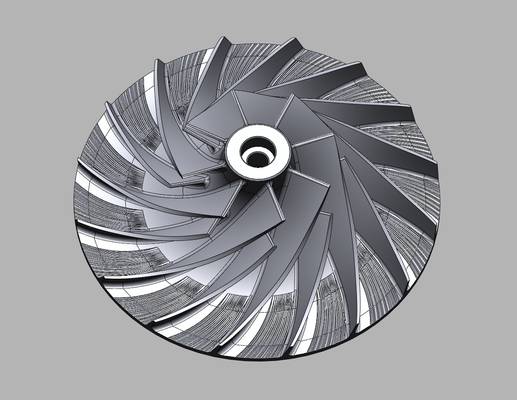
The range of production workpieces that benefit from this approach extends beyond precision housings. Investment castings with complex curved surfaces, injection-molded components with textured finishes, and sheet metal brackets with spring-back variability all share the same need: a measurement method that captures the surface as a whole, not as a handful of isolated points.
INSVISION’s technology portfolio, backed by ISO 9001 and CNAS-recognized calibration processes, positions the AlphaScan as a tool that fits between a quick shop-floor check and a formal metrology report. The data density is high enough for first article inspection; the speed is practical enough for in-process monitoring.
The missing piece is not the technology, but the habit of relying on point-based sampling when the part geometry demands a surface-based answer. For thin walls, deep pockets, and reflective machined finishes, the answer is increasingly clear.
Hangzhou Insvision Technology Co.,Ltd.
Address: Building 1, No. 1399 Liangmu Road, Yuhang District, Hangzhou, Zhejiang 311121, China