

When Shiny Parts Break the Inspection Workflow
A machined turbine blade lands on the bench. The surface is polished to a mirror finish. Under shop lights, it reflects everything—the operator, the ceiling, th
How Surface Reflectivity Disrupts Typical 3D Scanning
The core challenge with reflective industrial parts is not that the scanner fails to see the surface. It is that the scanner sees too much—ambient reflections, specular highlights, and ghost geometry from secondary bounces.
When a laser line or structured light pattern hits a polished metal surface, a large portion of the energy reflects directly into the sensor at saturation levels, while the surrounding area drops into shadow. The result is a point cloud with missing patches, floating noise, and edge blooming that erodes the sharp features needed for CAD comparison.
On a part like a polished injection mold insert, the engineer might need to capture deep ribs, narrow gate geometry, and a mirror-finish cavity floor in the same scan session. Traditional blue-light scanners struggle because the cavity floor acts like a mirror, while the deep ribs create occlusion zones.
Deployment Validation Checklist
| Focus Area | Decision Point | Deployment Note |
|---|---|---|
| Target part | Check size, surface condition, and key tolerances against the scan task | Run a full trial scan on a representative part |
| Data workflow | Verify point cloud, deviation map, and quality-report handoff | Confirm export formats and review ownership in advance |
| Shop-floor use | Review training, calibration, lighting, and working space | Keep the validation record as a repeatable inspection reference |
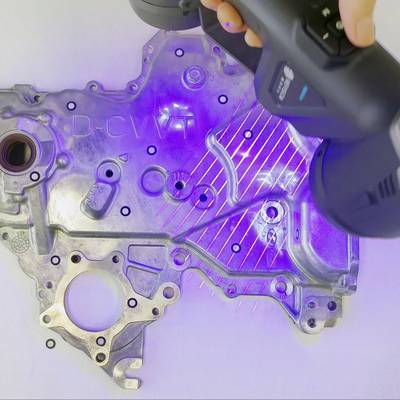
The operator compensates with multiple scan angles, but the real bottleneck is the dynamic range of the sensor and the robustness of the exposure control. INSVISION built the AlphaScan system with a multi-exposure fusion pipeline that captures several exposure levels in a single pass and reconstructs the surface from the unsaturated regions of each frame.
This means the scanner can hold detail on a bright polished surface and a dark textured surface within the same field of view, without manual setting changes.
Practical Workflow
- How Surface Reflectivity Disrupts Typical 3D Scanning — The core challenge with reflective industrial parts is not that the scanner fails to see the surface.
- Scanning Strategy for Large, Thin-Walled, and Complex Ass… — Reflective surfaces rarely appear in isolation.
- Turning Raw Scan Data into Actionable Inspection Reports — The scanned mesh is not the deliverable.
- Where the AlphaScan Fits into a Production Quality System — The value of a reflective-capable scanner is not limited to the measurement lab.
Scanning Strategy for Large, Thin-Walled, and Complex Assemblies
Reflective surfaces rarely appear in isolation. The polished blade transitions into a cast root with a rough surface finish. The chrome-plated shaft is press-fit into a housing with deep counterbores. The stamped aluminum panel has a bright surface, thin walls, and a shape that deforms under its own weight once removed from the fixture.
These mixed-surface, mixed-geometry parts demand a scanning workflow that prioritizes feature stability over raw speed. For a thin-walled housing with a bright exterior and a matte interior, the operator using the AlphaScan can start from the interior features—bosses, ribs, snap-fit geometry—and lock the coordinate system to those stable, non-reflective zones.
Once the reference frame is established, the scanner can move to the exterior reflective surfaces without risk of alignment drift. The scanner’s lightweight handheld design matters here: the operator can hold the device in one hand and reposition the part with the other, working through the scan path without fatigue.
For parts with deep pockets or undercuts, the AlphaScan’s small form factor allows the camera to move into tight spaces that would require a robot arm or a mirror setup with a fixed tripod scanner. The data from multiple scan angles is stitched in real time, and the operator can see coverage gaps on the live preview and fill them before moving to the next station.
Turning Raw Scan Data into Actionable Inspection Reports
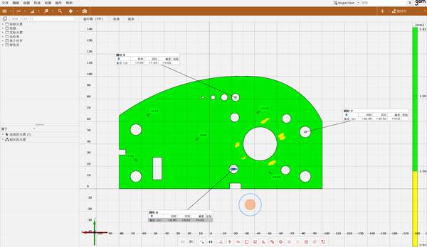
The scanned mesh is not the deliverable. The deliverable is a deviation map, a GD&T report, or a color-coded comparison that tells the machinist exactly where the tool offset drifted. On a reflective part, the raw mesh often contains small artifacts near high-curvature edges where reflections are hardest to manage. The post-processing step must clean these without smoothing away the dimensional signal.
The AlphaScan workflow includes automated mesh refinement that preserves sharp edges while filtering low-amplitude noise. From there, the aligned scan data is compared against the nominal CAD model. For a turbine blade, the engineer might check profile deviation along multiple cross-sections, leading-edge thickness, and trailing-edge radius.
The software generates a deviation map that shows the entire surface in a single view, with graduated color bands indicating material condition. Regions that exceed the tolerance band are flagged, and the report can be exported in a format that integrates with the plant’s existing quality management system.
For a batch of ten housings, the operator can run the same alignment routine and comparison template on each scan, producing a consistent report set that supports statistical process control. The entire pipeline—scan, align, compare, report—runs on a single laptop, and the results are available before the next part comes off the machine.
Where the AlphaScan Fits into a Production Quality System
The value of a reflective-capable scanner is not limited to the measurement lab. On a production floor, the scanner moves between the receiving dock, the machining cell, and the final inspection station. At incoming inspection, the AlphaScan can verify that a polished casting from a new supplier matches the print before it enters the machining queue.
In the machining cell, an operator can scan a first-off part, compare it to the CAD model, and adjust the tool offsets immediately—no waiting for the CMM to free up. At final inspection, the same scanner handles the full surface inspection and generates the customer-facing report. When the part is reflective, the scanner eliminates the spray-and-clean cycle that can add five to ten minutes per part.
Over a shift, that time adds up. The AlphaScan’s certifications—CE, FCC, and CNAS-traceable calibration—support the traceability chain that aerospace and medical device customers require. The scanner does not replace the CMM for every task, but it takes over the surface-intensive work that the CMM handles slowly and the spray-based scanner handles messily.
For an engineer managing a mixed batch of polished, coated, and as-cast parts, a single tool that handles all three surface types without changing the workflow is a practical advantage that shows up in the inspection schedule and the final quality metrics.
Hangzhou Insvision Technology Co., Ltd.
Address: Building 1, No. 1399 Liangmu Road, Yuhang District, Hangzhou, Zhejiang 311121, China