

When Metal Parts Resist Traditional Measurement: A 3D Scanning Workflow for Complex Geometries
## The Challenges Metal Components Bring to the Scanning Table Metal parts rarely arrive at the inspection station as simple prismatic shapes. Automotive powert
The Challenges Metal Components Bring to the Scanning Table
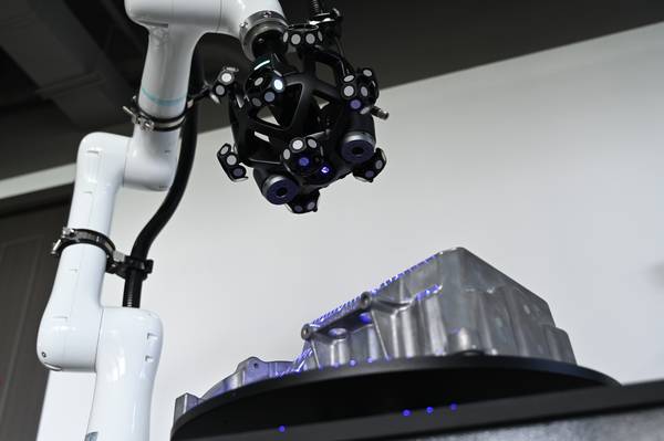
Metal parts rarely arrive at the inspection station as simple prismatic shapes. Automotive powertrain housings, aerospace structural brackets, and die-cast mold inserts carry a mix of freeform surfaces, deep pockets, thin ribs, and tight bolt patterns that challenge both contact probes and traditional optical devices. The geometry is only half the story.
Many production components have machined surfaces that reflect light unevenly or as-cast skins that are dark and matte, absorbing laser energy. Operators often face a combination of shiny milled faces, dull sand-cast texture, and fine edges that need to be captured in a single scan session without moving the part to a different fixture.
Deployment Validation Checklist
| Focus Area | Decision Point | Deployment Note |
|---|---|---|
| Target part | Check size, surface condition, and key tolerances against the scan task | Run a full trial scan on a representative part |
| Data workflow | Verify point cloud, deviation map, and quality-report handoff | Confirm export formats and review ownership in advance |
| Shop-floor use | Review training, calibration, lighting, and working space | Keep the validation record as a repeatable inspection reference |
Practical Workflow
- The Challenges Metal Components Bring to the Scanning Tab… — Metal parts rarely arrive at the inspection station as simple prismatic shapes.
- Designing a Scanning Strategy Around the Part, Not the Sc… — A practical workflow starts by categorizing the part’s features into zones of accessibility and difficulty.
- From Point Cloud to Quality Report: Closing the Data Loop — Raw point cloud data is only the starting point.
Dimensional control becomes even more difficult when the part is thin-walled or prone to springback. Sheet metal brackets, stamped enclosures, and welded assemblies can flex under clamping pressure, so the measurement setup must isolate the part without distorting it. In addition, small-diameter bores, internal threads, and undercut regions demand line-of-sight access that many fixed CMM routines cannot provide.
Casting and forging houses also need to verify stock allowance and draft angles, often on the shop floor, where temperature swings and vibration push the limits of measurement stability. All these factors mean the scanning process must be planned around the specific material, surface condition, and structural behavior of the metal component, not just the scanner’s published specifications.
Designing a Scanning Strategy Around the Part, Not the Scanner
A practical workflow starts by categorizing the part’s features into zones of accessibility and difficulty. Large flat or gently curved regions can be captured quickly with a handheld scanner at a generous standoff distance. High-risk areas—deep slots, narrow flanges, and sharp internal corners—demand closer passes and multiple approach angles.
For dark or oxidized metal surfaces, modern scanners that use blue laser light often maintain signal without requiring developer spray, which reduces prep time and eliminates the risk of residue affecting downstream assembly.
Changing the tilt of the scanner head and the distance to the surface helps the sensor collect enough data even on glossy coatings, provided the operator watches the live point cloud feedback and revisits areas where reflections cause dropouts.
Photogrammetry targets or magnetic markers become essential when the part is larger than a single scan volume or has features on multiple sides. By placing encoded points around the component before scanning, the software can stitch individual scans into a unified coordinate system with minimal accumulated error.
For thin-walled fabrications, it is often better to scan the part in a free state, supported on soft pads that mimic the assembly condition rather than clamping it rigidly. The scanner captures the as-built shape, and later, deviation analysis against the CAD model reveals exactly how much the part deforms compared to the nominal design.
This approach turns a geometric weakness into a measurement insight, helping teams decide whether to adjust the forming process or update the tolerance stack.
From Point Cloud to Quality Report: Closing the Data Loop
Raw point cloud data is only the starting point. After pruning noise and aligning multiple scans, the mesh must be compared to the reference CAD model.
A dedicated inspection software environment, such as SMARPARA Q, allows users to perform an initial best-fit alignment, then switch to datum-based alignment using functional surfaces—datum planes, pin holes, and locating slots—that replicate how the part is held in the next production stage.
GD&T tools inside the software evaluate profile, flatness, and position tolerances directly on the scan data, producing color-coded deviation maps that highlight out-of-spec regions in a single glance. This visual feedback is far more actionable than a table of numbers, especially for teams that need to decide whether to rework a die or adjust CNC offsets.
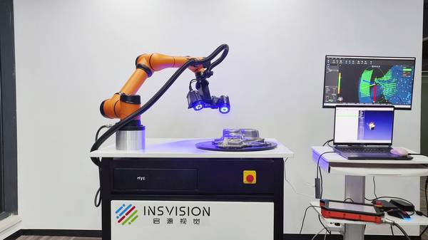
The report generation stage is what turns a scanning session into a traceable quality record. Rather than exporting static screenshots, the software can produce formatted reports with user-defined view angles, tolerance bands, and pass/fail histograms. When a batch of parts is scanned, the same alignment and inspection template can be reapplied, ensuring consistency across dozens or hundreds of units.
If a deviation pattern emerges—say, a consistent wall thickness shift in a certain cavity—the data can be fed back to the mold maintenance team before the next production run.
Hangzhou Insvision Technology Co.,Ltd.
Address: Building 1, No. 1399 Liangmu Road, Yuhang District, Hangzhou, Zhejiang 311121, China