

When Mechanical Parts Have No Drawings: Reverse Engineering Through 3D Scanning
Metal parts that have been in service for years rarely arrive on a workbench with a tidy CAD file. Pumps, gear housings, and mounting brackets from legacy equip
The Geometry and Material Spectrum of Legacy Mechanical Parts
Mechanical components that make their way into reverse engineering workflows span a wide range. Cast iron pump housings may have complex internal volutes, draft angles, and rough as‑cast surfaces. Stainless steel brackets often combine flat mounting faces with tight‑radius bends and punched holes.
Aluminum die‑cast parts for fitness equipment or automotive assemblies bring thin ribs, snap‑fit features, and smooth cosmetic surfaces that can throw off a laser. Cold rolling mill rolls, found in steel plants, are large cylindrical bodies where the entire functional surface is a precision‑ground profile. Each of these parts presents a different mix of scale, reflectivity, and feature density.
A part may be 200 mm long or 2 meters long. It may be coated in matte paint or left with a bright machined finish that acts like a mirror under structured light. The material itself — whether steel, cast iron, brass, or aluminum — influences how a 3D scanner reads the surface, and therefore how much preparation is needed before the first scan.
Deployment Validation Checklist
| Focus Area | Decision Point | Deployment Note |
|---|---|---|
| Target part | Check size, surface condition, and key tolerances against the scan task | Run a full trial scan on a representative part |
| Data workflow | Verify point cloud, deviation map, and quality-report handoff | Confirm export formats and review ownership in advance |
| Shop-floor use | Review training, calibration, lighting, and working space | Keep the validation record as a repeatable inspection reference |
Scenario Snapshot
A practical way to read the article is through this scenario:
- The Geometry and Material Spectrum of Legacy Mechan…: Mechanical components that make their way into reverse engineering workflows span a wide range.
- Where Measurement Gets Difficult: Surface, Size, an…: The hardest parts to reconstruct are not always the most intricate.
- Scanning Strategy: From Setup to Full Data Capture: A workable scan strategy starts with the part’s function.
Where Measurement Gets Difficult: Surface, Size, and Deformation
The hardest parts to reconstruct are not always the most intricate. Deep bores, blind holes, and internal threads hide from line‑of‑sight scanners. A bearing housing with a 40 mm bore and a 150 mm depth is a classic problem: the scanner sees the rim, but the walls disappear into shadow. Thin‑walled components, like a connecting frame for fitness equipment made from formed sheet metal, can flex under their own weight.
If the part is not held in a stable fixture, the scan data will capture a deformed shape rather than the intended free‑state geometry. Highly reflective surfaces — a polished shaft, a chrome‑plated hydraulic rod — create speckle noise that cheapens the point cloud. Dark rubber seals or oily gasket faces absorb light and produce low‑contrast data.
Parts that have been in operation bring another layer of trouble: wear, pitting, and corrosion mean that the as‑scanned surface is no longer the design surface. The engineer must decide whether to capture the worn state or to reconstruct the nominal geometry by extrapolating from undamaged areas.
Scanning Strategy: From Setup to Full Data Capture
A workable scan strategy starts with the part’s function. The mounting faces, shaft axes, and mating surfaces that define the part’s role in the assembly are the features that must be captured with the highest accuracy. For a cold rolling roll, the entire cylindrical surface is a working surface; a single good roll can serve as the master reference when no CAD model exists.
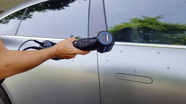
INSVISION’s AlphaScan handheld 3D scanner, with its blue laser technology, handles a broad range of surface conditions. The large scan area of 650 mm × 550 mm reduces the number of individual passes needed on big castings, while the scanner’s ability to maintain stable measurement results on shiny or dark surfaces cuts down on the need for spray coating.
The operator moves the scanner around the part, building the point cloud in real time. Areas that are shadowed — deep flanges, internal ribs — are targeted with angled passes and short‑range captures. The software flags gaps in the data, prompting the operator to revisit those zones before moving on. The goal is a complete, watertight mesh that captures every feature that matters.
Turning Point Clouds into CAD Models and Inspection Reports
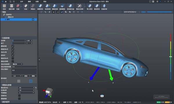
The raw point cloud is only the starting point. Inside INSVISION’s SMARPARA Q software, the data is aligned, cleaned, and turned into a mesh. For reverse engineering, the mesh is sectioned, and prismatic features — planes, cylinders, holes, pockets — are extracted and fitted.
The software’s GD&T tools allow the engineer to compare the scanned data against a nominal CAD model when one is being created, or to compare a worn part against a known good sample. The same workflow that produces a CAD model also produces a color‑mapped deviation report, showing exactly where the part is within or outside tolerance.
This report becomes the basis for deciding whether to reproduce the part as‑is, to add machining stock, or to adjust the design. For a fitness equipment connection frame, the scan‑to‑CAD process can replace a manual measurement cycle that used to take days with calipers and height gauges. The final output is a parametric CAD model that can be modified, documented, and handed off to CAM or 3D printing without ambiguity.
Bringing a mechanical part back to life without drawings is a chain of decisions that starts with the part itself. The material, surface finish, wall thickness, and functional geometry determine what can go wrong in scanning and what must go right.
With the AlphaScan handheld scanner and the SMARPARA Q software environment, INSVISION offers a pipeline that respects the nature of the part instead of treating every surface as a neutral white object. The result is a scan strategy that works on the shop floor, a point cloud that is dense where it matters, and a CAD model that is ready for the next step — whether that is inspection, remanufacturing, or a design update.
Hangzhou Insvision Technology Co.,Ltd.
Address: Building 1, No. 1399 Liangmu Road, Yuhang District, Hangzhou, Zhejiang 311121, China