

What Small-Part Inspection Actually Demands from a 3D Scanner
A small injection-molded connector housing, a turned brass bushing, or a stamped steel spring clip rarely announces its flaws in plain sight. The true inspectio
Understanding the Object Before Choosing the Scanner
Small manufacturing parts rarely present a single, uniform surface. A machined aluminum housing might have a matte bead-blasted exterior, a reflective bore face, and a deep threaded hole that drops into shadow. A black plastic electrical connector with a glossy finish absorbs light unevenly and often has tiny snap-fit features that are easy to miss.
Thin-walled stamped parts vibrate under even light probe contact, making traditional touch probing nearly useless without expensive fixturing. Before any scanning strategy is defined, the part’s material, surface condition, dimensional range, and geometric complexity must be assessed.
Dark, shiny, or transparent surfaces demand a scanner that can manage low contrast and high reflectivity without requiring heavy coating with developer spray. Parts with deep cavities or narrow slots need a scanner that captures shape from a short standoff and still maintains accuracy when the laser line wraps around internal edges.
Deployment Validation Checklist
| Focus Area | Decision Point | Deployment Note |
|---|---|---|
| Target part | Check size, surface condition, and key tolerances against the scan task | Run a full trial scan on a representative part |
| Data workflow | Verify point cloud, deviation map, and quality-report handoff | Confirm export formats and review ownership in advance |
| Shop-floor use | Review training, calibration, lighting, and working space | Keep the validation record as a repeatable inspection reference |
If the part is prone to flexing or distortion, the scanning method must be non-contact and fast enough to capture the as-is shape before the part is moved or re-clamped.
Designing a Scanning Strategy That Fits the Part
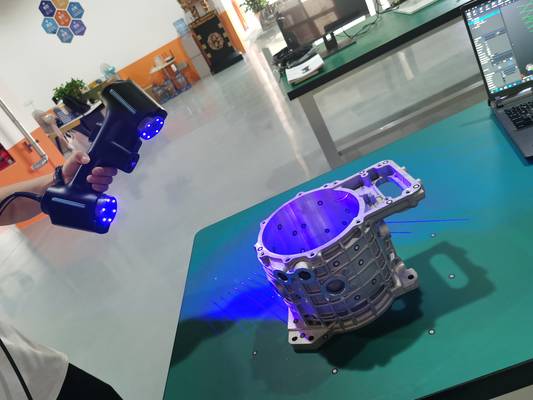
Once the part’s physical traits are mapped, the scanning workflow shifts from a generic “point and shoot” approach to a deliberate sequence. Handheld 3D scanners like the INSVISION AlphaScan use blue laser technology to handle reflective and dark surfaces without requiring a full coating of powder, which is a practical advantage when dealing with mixed-material assemblies.
The operator can start with a broad sweep at a working distance of around 300 mm, then move closer to capture boss features, ribbing, or clip details that define how the part actually mates in an assembly. For a part under 50 mm in length, the scan path must be planned to avoid excessive frame overlap that can introduce drift, while still obtaining enough feature data for the software to stitch scans accurately.
Companies often apply a few small adhesive targets on a fixture plate rather than directly on the part—this preserves the measured surface and provides a stable reference for alignment. Deep holes and threaded inserts require a separate pass with the scanner angled to allow the laser to reach the thread root.
The result is a dense point cloud, typically in the millions of points, that captures the nuances of parting lines, witness marks, and subtle surface warping that would otherwise go unnoticed.
Turning Point Cloud Data into Inspection Results
Raw scan data is not yet an inspection report. The point cloud must be cleaned, aligned to a reference coordinate system, and compared to the nominal CAD geometry. For small parts, the alignment step is critical because a 0.05 mm misalignment at the datum features can shift the entire color map of deviation and lead to false rejection of good parts.
The INSVISION SMARPARA Q software is built for this workflow, allowing direct import of the scan data and CAD model, alignment via best-fit or datum-based methods, and then a full geometric dimensioning and tolerancing (GD&T) analysis.
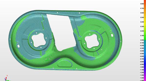
The software can output a deviation map that shows exactly where the part is out of spec, and it can generate a pass/fail report that includes cross-sectional analysis and specific dimension callouts. For a batch of small parts, the same alignment and analysis template can be reused, turning a 20-minute inspection routine into a repeatable process that runs in a few minutes per piece.
The report generated is not just a deviation value; it ties each measurement to the part’s actual coordinate system, making it clear whether the error is a form deviation, a positional shift, or a scaling issue.
Closing the Loop from Inspection to Process Control
The real value of 3D scanning for small parts emerges when the inspection data feeds back into the manufacturing process. A color map of a plastic connector showing consistent sink marks near a thick rib tells the mold maker exactly where to adjust cooling or packing pressure. A scan of a machined bracket that reveals a slight twist in the flange indicates that the clamping force during machining is deforming the part.
Because the AlphaScan handheld scanner captures the entire surface shape rather than a few discrete points, it uncovers these systematic patterns that traditional CMM probing might miss. After the process adjustment, a rescan of the same part, or a new sample from the line, can be compared using the same GD&T report template, and the before-and-after deviation maps can be overlaid to confirm the improvement.
This creates a closed loop where the scanner is not just a pass/fail gate but a diagnostic tool that helps reduce scrap and rework.
Manufacturers who work with small, high-precision parts often find that investing in a scanner that can handle their specific surface and geometry challenges—and that integrates with software designed for detailed inspection—is the difference between inspecting a part and actually understanding why it measured the way it did.
Hangzhou Insvision Technology Co.,Ltd.
Address: Building 1, No. 1399 Liangmu Road, Yuhang District, Hangzhou, Zhejiang 311121, China