

When a Bore Gauge No Longer Reaches Far Enough: Making Sense of Deep Cavity 3D Scanning
A deep cavity inspection order lands on the desk of a quality manager. The print calls out diameters, perpendicularity, and wall thickness inside a bore that ta
The challenge is not just about reach. Cavity interiors are optically hostile. A cast or machined bore may have a low-reflectivity surface from shot blasting, carbon deposits, or thin oil residue. Deep cavities trap ambient light poorly, and the scanner has to project structured light into a space where line-of-sight is limited and the working distance is tight.
If the part is a turbine housing, a hydraulic manifold, or an injection mold core, the cavity might also be hot from a prior process, vibrating slightly, or too large to fixture on a rotary table. These conditions do not excuse a missed tolerance.
Deployment Validation Checklist
| Focus Area | Decision Point | Deployment Note |
|---|---|---|
| Target part | Check size, surface condition, and key tolerances against the scan task | Run a full trial scan on a representative part |
| Data workflow | Verify point cloud, deviation map, and quality-report handoff | Confirm export formats and review ownership in advance |
| Shop-floor use | Review training, calibration, lighting, and working space | Keep the validation record as a repeatable inspection reference |
What changes the outcome is a scanning strategy that treats the internal cavity not as a single feature, but as a sequence of overlapping optical zones, each captured with a sensor and data path that preserves sub-millimeter accuracy from the opening all the way to the blind end.
Understanding What Makes a Cavity Difficult to Scan
Not every internal void is a deep cavity. A shallow pocket with a wide opening is straightforward for most structured-light scanners. The difficulty escalates when the cavity depth exceeds four times its smallest diameter, when the internal wall contains compound curvature, or when the opening is obstructed by a flange or a threaded boss. Surface condition matters just as much as geometry.
A polished internal bore can create specular reflections that confuse stereo matching, while a dark, porous cast surface absorbs light and starves the sensor of usable returns. Thermal expansion introduces another variable. A cavity measured while the part is still warm from machining will not match the CAD nominal once the part stabilizes at room temperature.
A responsible inspection plan must account for surface treatment, reflectivity range, and thermal state before the first scan is captured.
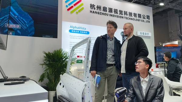
The AlphaScan handheld 3D scanner from INSVISION addresses these variables with a combination of blue laser projection and a high-frame-rate camera array that maintains point cloud density even when the sensor is angled into a confined opening. Instead of relying on a single exposure setting, the system adapts laser intensity and exposure on the fly.
When the beam hits a dark oxide layer at the bottom of a blind hole, the scanner compensates without requiring the operator to stop and recalibrate. In practice, this means a single scan session can cover the shiny machined entry bore, the rough-cast transition zone, and the anodized internal seat without switching acquisition modes or spraying the entire cavity with developer.
Scanning from the Outside In Without Losing Registration
The most common mistake in cavity scanning is starting at the deepest point and working outward. That approach severs the geometric relationship between the cavity and the rest of the part. A better sequence begins on the external reference surfaces — flat datum faces, dowel holes, machined pads — establishes a stable coordinate frame, and then moves the scanner progressively inward.
The AlphaScan maintains registration through feature tracking, using the part’s own external geometry as a continuous anchor. When the scanner’s field of view enters the cavity and the external features disappear from sight, the software relies on the previously mapped internal wall segments to hold alignment.
This requires a scanner that does not lose track during rapid transitions from bright external surfaces to dim internal ones, a condition that separates measurement-grade tools from lower-tier inspection cameras.
Operators working with deep cavities should plan a scan path that overlaps each pass by at least 30 percent. This overlap zone gives the alignment algorithm enough common geometry to stitch adjacent frames without drift. On a typical hydraulic valve body with a 200 mm deep spool bore, the scan path might start at the mounting flange, progress down the bore in a helical pattern, and finish at the internal seat.
The entire sequence takes under three minutes per cavity. If the cavity has cross-holes or intersecting galleries, those are captured in the same run by tilting the scanner axis to face the side openings. The resulting point cloud is a complete internal map, not a set of disconnected cross-section rings.
From Point Cloud to Dimensional Report in One Shift
Raw scan data is not an inspection report. The point cloud must be aligned to the CAD nominal, deviation color maps must be generated, and specific callouts — diameter, cylindricity, wall thickness, runout — must be extracted and compared against tolerance bands. INSVISION’s software pipeline handles this without exporting data to a third-party metrology package.
The operator imports the CAD model, performs a best-fit alignment using the external datum features, and then isolates the cavity region for a localized comparison. The software applies a 3D deviation map that shows exactly where the cast wall is too thin or where the machined bore exceeded its roundness limit.
Because the entire cavity is captured, wall thickness can be computed by offsetting the internal surface and intersecting it with the external skin, a measurement that is impossible with a single-point bore gauge.
For a production batch, the same scan-to-report workflow becomes a template. The first article takes longer because the operator defines the measurement zones and tolerance bands. Articles two through fifty run against that template, and the software flags any cavity that falls outside the predefined limits. The report includes a timestamp, a serial number, a pass/fail summary, and a link to the full deviation map.
A quality engineer reviewing the report can trace a specific out-of-tolerance zone back to the raw scan data without re-measuring the part. This traceability is critical for suppliers shipping to aerospace prime contractors or medical device OEMs, where a dimensional dispute can halt a shipment.
Matching the Scanner to the Cavity Without Overbuying
A cavity scanner is not a single specification. The right tool depends on the smallest opening diameter, the deepest reach required, and the surface conditions the system must handle. For cavities with openings above 80 mm, a standard field-of-view scanner with a mid-range standoff works well.
For openings below 50 mm, the scanner must maintain accuracy at a closer working distance, and the projection pattern must be fine enough to resolve small features on the internal wall.
The AlphaScan handheld configuration offers interchangeable scan modes that let the same device operate at different standoffs, so the user can switch between a wide field of view for external surfaces and a tighter, higher-density mode for internal bores. This flexibility removes the need to purchase a dedicated cavity scanner alongside a general-purpose unit.
The decision also involves the material mix. A foundry scanning cast iron manifolds, a machine shop inspecting aluminum valve bodies, and a mold shop verifying steel core cavities all face different reflectivity and absorption challenges. The scanner’s ability to handle that range without powder coating or manual surface preparation is a direct driver of throughput.
Every minute spent spraying and drying a cavity is a minute not spent measuring. INSVISION built the AlphaScan with a dynamic exposure system that reduces the need for surface treatment across metals, polymers, and composite materials. When a cavity must be scanned in its as-machined, as-cast, or as-assembled state, the scanner’s optical head does the adapting, not the operator.
That approach keeps the inspection cycle inside the same shift and limits the number of variables that can introduce measurement error before the dimensional report reaches the production supervisor.
Hangzhou Insvision Technology Co., Ltd.
Address: Building 1, No. 1399 Liangmu Road, Yuhang District, Hangzhou, Zhejiang 311121, China