

Mastering the Challenge of 3D Scanning Small Precision Parts
It happens in every metrology lab and on every quality control bench: an engineer places a connector pin, a tiny orthopedic screw, or a fuel injector nozzle und
The real difficulty is not simply capturing a point cloud of a small object. It is capturing the right data with sufficient density, edge sharpness, and geometric fidelity to make accept/reject decisions that hold up in an audit.
Small parts demand a scanning strategy that accounts for material optical properties, fixturing repeatability, and the computational path from raw scan data to a color-mapped deviation report stored in a quality management system.
Deployment Validation Checklist
| Focus Area | Decision Point | Deployment Note |
|---|---|---|
| Target part | Check size, surface condition, and key tolerances against the scan task | Run a full trial scan on a representative part |
| Data workflow | Verify point cloud, deviation map, and quality-report handoff | Confirm export formats and review ownership in advance |
| Shop-floor use | Review training, calibration, lighting, and working space | Keep the validation record as a repeatable inspection reference |
INSVISION has developed its handheld scanning portfolio to address these constraints directly, with the AlphaScan and AlphaVista systems serving as the data acquisition front end for workflows that blend precision metrology with practical shop-floor usability.
Reading the Object: How Geometry, Surface, and Material Drive Scanning Decisions
Every small precision part presents a unique combination of challenges before a single scan is taken. A polished stainless steel micro-gear reflects structured light differently than a black PEEK plastic housing, and a ceramic capillary tube absorbs light in ways that cast metal parts never do. The first step in building a reliable inspection routine is characterizing the object itself.
Diameters below five millimeters create severely limited line-of-sight, forcing the scanner to capture high-density data from very short working distances. Thin walls under 0.3 millimeters introduce vibration and thermal drift issues, where even the heat from an operator’s hand can shift geometry enough to throw a scan out of tolerance.
High-aspect-ratio features such as deep counterbores or cross-drilled holes create shadow zones where blue light cannot reach without multiple angled scans and careful part orientation.
Practical Workflow
- Reading the Object: How Geometry, Surface, and Material D… — Every small precision part presents a unique combination of challenges before a single scan is taken.
- Scanning Strategy: From Single Captures to Full Part Enve… — A productive scan routine for small parts is built around the concept of data sufficiency rather than maximum point density.
- Closing the Data Loop: Alignment, Inspection, and Actiona… — Raw point cloud data is only as valuable as the decisions it enables.
- Where Small Part Scanning Delivers the Highest Return — The application space for small part 3D scanning extends well beyond the obvious quality control use cases.
Surface finish and optical behavior often matter more than absolute size. Fine lathe-turned surfaces with Ra values below 0.2 microns act like partial mirrors, sending fringe patterns scattering in unpredictable directions. Translucent silicone seals or sapphire windows require a different approach entirely, as the light penetrates the surface rather than reflecting cleanly from it.
INSVISION’s AlphaVista uses blue-light structured-light technology as its core principle, projecting a precise fringe pattern onto the surface and capturing the deformation with stereo cameras. The blue wavelength limits ambient light interference and improves edge definition on reflective surfaces.
For darker or diffuse materials, adjusting the projector intensity and exposure settings at the software level often eliminates the need for spray coatings, though in some cases a thin layer of developer remains the pragmatic choice to maintain scan speed and data completeness.
Scanning Strategy: From Single Captures to Full Part Envelopes
A productive scan routine for small parts is built around the concept of data sufficiency rather than maximum point density. The goal is to capture every functional surface, every datum feature, and every critical edge with enough resolution to support a meaningful comparison against the nominal CAD model.
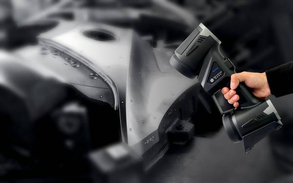
Handheld scanners like the AlphaScan allow operators to move around the part, tilting the scanner to capture steep sidewalls, undercut features, and the bottom faces of flanges that would be invisible from a single fixed angle. The scanner’s lightweight build and ergonomic grip reduce fatigue during long inspection sessions, particularly when batches of fifty or more parts must be scanned in a single shift.
Fixturing is a critical and often underestimated element of the process. A small part must be held rigidly enough to avoid movement between scans, yet the fixture itself must not obscure features or create hard-to-clean shadow regions. Magnetic holders, soft-jaw vices with kinematic mounts, and custom 3D-printed nests are common solutions.
The part is placed on a turntable or positioned manually, and the operator performs a series of overlapping scans, maintaining a consistent standoff distance and ensuring at least 30 percent overlap between adjacent frames. The software stitches the frames in real time, building a complete 3D mesh.
For deep holes or internal threads, a separate high-resolution scan pass with adjusted exposure settings can pull out detail that the broader scan might miss. INSVISION’s software platform supports these iterative loops, flagging areas of low point density and prompting the operator to re-scan specific zones before the data is finalized.
Closing the Data Loop: Alignment, Inspection, and Actionable Reporting
Raw point cloud data is only as valuable as the decisions it enables. The transition from scan data to inspection result follows a structured workflow that begins with alignment. The scanned mesh is registered to the nominal CAD model using a combination of datum features, best-fit algorithms, and reference geometry.
For parts with tight positional tolerances, a 3-2-1 alignment based on the actual datum structure specified on the engineering drawing is mandatory. After alignment, a full surface comparison generates a color-mapped deviation plot, where red zones indicate material above the nominal surface, blue zones show material below, and green zones fall within the specified tolerance band.
The inspection report must serve multiple audiences. A manufacturing engineer might want to see a histogram of deviation values across the entire production batch to detect gradual tool wear. A quality manager needs traceable documentation linked to part serial numbers and timestamped scan data. A design engineer needs cross-sectional comparisons at specific planes to verify wall thickness or draft angles.
INSVISION’s software exports these reports in formats that integrate with existing quality systems, including PDF reports with embedded 3D views, CSV files of point-by-point deviations, and mesh data exportable to third-party analysis software.
The whole workflow, from scanning the first part to generating a signed inspection report, can be completed in minutes rather than the hours required for CMM programming and tactile measurement.
Where Small Part Scanning Delivers the Highest Return
The application space for small part 3D scanning extends well beyond the obvious quality control use cases. In medical device manufacturing, bone screws, dental implants, and biopsy forceps must meet strict FDA and ISO 13485 documentation requirements. 3D scanning provides the full surface data that a touch probe cannot, and it does so without contact forces that could scratch or deform delicate features.
INSVISION holds ISO 9001, ISO 14001, and ISO 45001 certifications, and its products carry CE and FCC marks, which supports compliance requirements in regulated industries.
In aerospace fuel system components, where swirl chambers and metering orifices determine combustion efficiency, the ability to verify internal geometry through a combination of external scans and strategic sectioning eliminates guesswork from the development process.
The electronics supply chain benefits from the same technology when inspecting micro-connectors, EMI shielding cans, and precision stampings. These parts are often produced in high volumes with very narrow process windows, and a single scan can capture dozens of critical dimensions simultaneously. The data feeds back into tool maintenance schedules, press setup adjustments, and supplier quality audits.
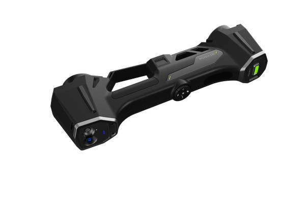
For mold and die makers, scanning a small molded gear or a silicone gasket provides the as-built geometry needed to compensate for shrinkage and warpage before the mold is finalized. The AlphaScan and AlphaVista systems, with their handheld form factors and structured-light accuracy, slot into these workflows without requiring a dedicated metrology room.
The scanner can travel to the press, the molding machine, or the assembly station, bringing inspection data directly to the point of production. As parts continue to shrink and tolerances continue to tighten, the ability to acquire full-field surface data quickly and repeatably is moving from a competitive advantage to a baseline requirement for any precision manufacturing operation.
Hangzhou Insvision Technology Co., Ltd.
Address: Building 1, No. 1399 Liangmu Road, Yuhang District, Hangzhou, Zhejiang 311121, China