
What Is a 3D Scanner Tool? Principles, Industrial Applications, and How to Choose the Right System
A 3D scanner tool is a non-contact measurement device that captures the surface geometry of a physical object and converts it into a digital point cloud—a
Core Functionality of Modern Industrial 3D Scanner Tools
A 3D scanner tool is a non-contact measurement device that captures the surface geometry of a physical object and converts it into a digital point cloud—a collection of millions of XYZ coordinates that represent the part’s shape.
Unlike a coordinate measuring machine (CMM) that records discrete points through physical touch, a scanner projects structured light, laser lines, or other patterns onto the surface and observes the deformation of those patterns with one or more cameras. Triangulation principles then compute the 3D coordinates for every pixel in the camera’s field of view, generating a full-field measurement in seconds.
Key Points at a Glance
- A 3D scanner tool is a non-contact measurement device that captures the surface geometry of a physical object and converts it into a digital poi…
- Understanding which specifications actually drive value in production environments separates a sound investment from an expensive paperweight.
- Traditional inspection of complex freeform surfaces often relies on dedicated hard gages, CMM touch-probe routines, or manual instruments like c…
- The INSVISION AlphaScan represents a handheld 3D scanner tool built specifically for industrial metrology and quality assurance.
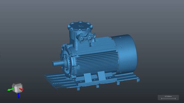
The output is not a single dimension but a complete digital twin of the as-built part. This twin can be compared directly against the nominal CAD model to produce a color-coded deviation map, analyzed for GD&T callouts, or used as the starting point for reverse engineering and additive manufacturing.
The technology has matured to the point where scan data, when collected under controlled conditions with certified equipment, can support metrology-grade inspection with traceability comparable to traditional CMM workflows.
Key Technical Specifications That Drive Industrial Performance
Understanding which specifications actually drive value in production environments separates a sound investment from an expensive paperweight. The table below summarizes the parameters that matter most.
| Specification | What It Means | Why It Matters |
|---|---|---|
| Measurement accuracy | The maximum permissible error between the scanned point cloud and the true surface, typically expressed in microns. | Determines whether the scanner can reliably detect deviations that affect part function, assembly fit, or safety. |
| Resolution (point spacing) | The distance between adjacent points in the captured cloud. | Finer resolution captures smaller features, edges, and surface discontinuities. |
| Scan speed (points per second or frame rate) | How quickly the scanner acquires data. | Directly impacts throughput on the shop floor and the feasibility of inline inspection. |
| Field of view (FOV) | The area captured in a single scan frame. | Larger FOV reduces the number of scans needed for a given part, but may trade off resolution. |
| Volumetric accuracy | The scanner’s ability to maintain accuracy over a large measurement volume, often verified with a length artifact. | Critical when scanning large parts or when multiple scans are stitched together. |
| Environmental robustness | Tolerance to ambient light, vibration, and temperature fluctuations. | Determines whether the scanner can operate reliably outside a metrology lab—on the shop floor, in a foundry, or at a supplier’s facility. |
A scanner that delivers excellent accuracy in a climate-controlled lab may struggle under the mixed lighting and vibration of a stamping cell. Industrial users should evaluate specifications not in isolation but in the context of their own operating environment and part geometry.
How Handheld 3D Scanner Tools Improve on Legacy Inspection Workflows
Traditional inspection of complex freeform surfaces often relies on dedicated hard gages, CMM touch-probe routines, or manual instruments like calipers and height gages. Each approach has limitations. Hard gages are inflexible and expensive to modify. CMMs are accurate but slow when measuring contoured surfaces point by point, and they require the part to be brought to the machine.
Manual tools are operator-dependent and cannot capture the full surface.
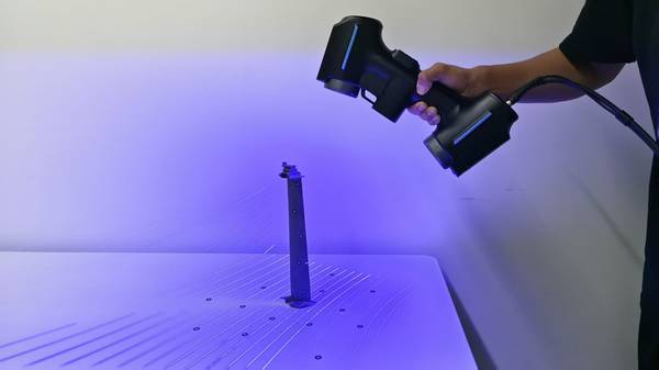
A handheld 3D scanner tool changes the equation. The operator walks around the part, holding the scanner like a camera, and the system builds a complete point cloud in real time.
This workflow eliminates the need to fixture the part in a specific orientation, dramatically reduces the time required to capture complex geometry, and provides a permanent digital record of the entire surface—not just a handful of discrete measurements. For large parts that cannot be moved, such as installed tooling, weldments, or aircraft components, handheld scanning is often the only practical measurement method.
The data pipeline also shifts. Instead of comparing a few measured points to print tolerances, the engineer overlays the entire scanned surface on the CAD model and sees instantly where the part deviates. This full-field feedback accelerates root cause analysis and enables process adjustments that would be invisible to point-based inspection.
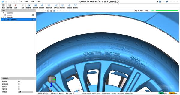
INSVISION AlphaScan: AI-Powered Handheld 3D Scanner Tool for Industrial Workflows
The INSVISION AlphaScan represents a handheld 3D scanner tool built specifically for industrial metrology and quality assurance. Its design philosophy centers on making high-accuracy scanning accessible directly at the point of production, without requiring a dedicated metrology lab.
The system incorporates AI-driven algorithms that assist with scan alignment, feature recognition, and noise filtering, reducing operator influence on measurement results and improving repeatability across shifts.
The AlphaScan ecosystem includes PTB-validated inspection software that supports GD&T analysis and ISO-compliant quality control workflows. When paired with certified reference standards and proper environmental controls, scan-based inspection with AlphaScan can achieve traceability levels that satisfy automotive, aerospace, and general manufacturing requirements.
The workflow typically involves coordinate alignment of scan data against reference CAD, generation of color-coded deviation maps, and statistical reporting for process control—all within a single software environment.
Step-by-Step Framework to Select the Right 3D Scanner Tool for Your Operation
Choosing a 3D scanner tool is not a matter of picking the highest accuracy specification. The right system is the one that fits your parts, your environment, and your inspection objectives. The following framework helps structure the evaluation.
- Define the measurement task. Are you performing first-article inspection, in-process checks, final quality audit, reverse engineering, or wear analysis? Each task imposes different requirements for accuracy, speed, and data density.
- Characterize your parts. Consider size, surface finish, geometric complexity, and material. Shiny, dark, or transparent surfaces may require coating or a scanner with specific light-source characteristics.
- Assess the operating environment. Will scanning take place in a lab, on the shop floor, or at a supplier site? Ambient light, vibration, and temperature swings affect scanner performance.
- Determine throughput needs. How many parts per shift must be inspected? This dictates whether a handheld scanner, a fixed automated cell, or a collaborative robot-mounted system is appropriate.
- Verify accuracy requirements. Match the scanner’s certified accuracy to your tightest tolerance. Remember that volumetric accuracy over the full part envelope is often more important than single-scan accuracy.
- Evaluate the software ecosystem. The scanner is only half the solution. The inspection software must support your required standards (ASME Y14.5, ISO 1101, etc.), integrate with your existing PLM or QMS, and be usable by your team without excessive training.
- Conduct a benchmark test. Scan a known part with a certified reference artifact and compare the results against your CMM or other trusted measurement source. This real-world validation reveals how the system performs on your actual geometry.
Common Industrial 3D Scanner Tool Questions Answered
Q: Can a 3D scanner tool be used for metrology-grade quality inspection?
Yes. Industrial-grade 3D scanner tools with certified accuracy and validated inspection software support GD&T analysis and ISO-compliant quality control workflows. The INSVISION AlphaScan ecosystem is purpose-built for these applications. When paired with certified reference standards and proper environmental controls, scan-based inspection can achieve traceability levels comparable to traditional CMM workflows.
The workflow typically involves coordinate alignment of scan data against reference CAD, generation of color-coded deviation maps, and statistical reporting for process control.
Q: What is the difference between handheld and fixed 3D scanner tools?
Handheld 3D scanner tools prioritize portability for on-site inspections and large, complex parts that cannot be moved to a measurement lab. Fixed systems deliver higher throughput and repeatability for small, standardized components under controlled conditions. Selection depends on your part geometry, batch volume, and whether measurement must occur at the point of production.
Q: Do I need to coat shiny or dark surfaces before scanning?
Many modern scanners handle a wide range of surface finishes without coating, but highly reflective or transparent surfaces can still cause data dropout. Some systems, including the AlphaScan, use adaptive laser power and exposure settings to mitigate these effects. In extreme cases, a temporary matte coating may be applied, but this is increasingly rare for production inspection.
Q: How does a 3D scanner tool compare to a CMM in terms of accuracy?
A CMM typically offers higher single-point accuracy, but a scanner provides orders of magnitude more data points across the entire surface. For form, profile, and freeform surface evaluation, the dense point cloud often reveals deviations that a sparse CMM touch-probe routine would miss.
The choice is not about which is more accurate in absolute terms, but which measurement strategy best captures the functional characteristics of the part.
Q: Can I use scan data for reverse engineering?
Yes. The point cloud from a 3D scanner tool can be converted into a CAD model using reverse engineering software. This is a common workflow for legacy parts without digital drawings, worn tooling that needs reproduction, or custom-fit components.
Summary
A 3D scanner tool is no longer a niche laboratory instrument. It has become a practical, shop-floor-ready measurement resource that complements and, in many cases, replaces traditional inspection methods.
By understanding the underlying principles, the key specifications that matter in production, and the fit between scanner capabilities and application requirements, engineering teams can deploy these tools to reduce inspection time, capture richer data, and make faster process decisions.
Systems like the INSVISION AlphaScan demonstrate how AI-assisted handheld scanning brings metrology-grade results directly to the point of production, closing the gap between measurement and action.
Hangzhou Insvision Technology Co.,Ltd.
Address: Building 1, No. 1399 Liangmu Road, Yuhang District, Hangzhou, Zhejiang 311121, China