
How 3D Scan Targets Improve Handheld Metrology Accuracy and When to Use Them
Learn how 3D scan targets enable stable global alignment in handheld 3D scanning, when to use them over feature-only alignment, and INSVISION AlphaScan capabilities.
Handheld 3D scanners have moved from niche reverse-engineering tools to everyday instruments on shop floors, quality labs, and field service trucks. Yet a persistent question follows every new deployment: when do you need to place physical targets on a part, and when can you rely on the part’s own geometry to stitch scans together?
The answer sits at the intersection of metrology fundamentals, surface conditions, and the tolerance stack-up a team is willing to accept.
This article unpacks the role of 3D scan targets in handheld metrology. It explains how they work, what makes a target system reliable, where target-assisted alignment outperforms feature-only methods, and how to decide whether targets belong in your workflow.
Along the way, it describes how INSVISION’s AlphaScan platform implements target detection to give engineers a flexible, measurement-grade toolset without locking them into a single alignment strategy.
What 3D Scan Targets Are and How They Work
A 3D scan target is a physical reference marker placed on or around a part before scanning. Most metrology-grade targets use retroreflective material—a surface engineered to return light directly toward its source with minimal scattering. When a handheld scanner’s laser or structured light hits a retroreflective dot, the sensor receives a strong, concentrated return signal.
The scanner’s software identifies the centroid of that return and treats it as a fixed coordinate in space.
During a multi-pose scan, an operator moves around a part, capturing overlapping point clouds from different angles. Each new scanner position introduces small rotational and translational errors. Without external references, those errors accumulate. On a part longer than a meter—a turbine blade, a large casting, an injection mold—drift can push the final alignment outside tolerance by several millimeters.
Standards such as ISO 10360-8 provide frameworks for verifying optical 3D measurement systems, and target-based alignment directly addresses the drift problem by giving the software a set of invariant points that tie all scans into a common coordinate system.
The underlying mathematics is bundle adjustment. The software simultaneously refines scanner poses and target coordinates so that the reprojection errors across all observations are minimized. Targets distributed across multiple planes and with good angular diversity produce a stronger geometric solution than targets clustered in a small area. This is why target placement is not arbitrary—it is a metrology decision.
What Makes a 3D Scan Target System Reliable
Not all reflective dots perform equally. In industrial environments, four factors separate a robust target system from one that introduces its own errors.
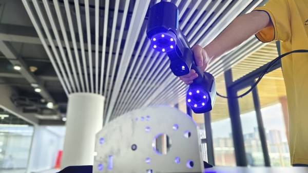
Spectral matching. Handheld scanners using blue laser sources—such as the 30/42 blue laser configuration in INSVISION’s AlphaScan—operate around 450 nm. Retroreflective film must have its peak reflectivity tuned to that wavelength. A target optimized for red or infrared lasers will return a weaker signal, reducing the signal-to-noise ratio and making centroid detection less precise.
Dimensional stability. The target’s physical geometry matters. Tight dimensional tolerances on the dot diameter and circularity support the scanner’s ability to locate the centroid repeatably. For a system specified with a stable accuracy of 0.020 mm, the target itself must not become the limiting factor.
Environmental resilience. Shop floors are not calibration labs. Targets must survive temperature swings, coolant mist, and handling. INSVISION’s targets are designed to resist degradation across an operating range of -10 °C to 40 °C, maintaining adhesion and reflectivity through extended scanning sessions.
Intelligent filtering. A retroreflective return is not always a valid target. Ambient metallic surfaces, wet spots, or polished tooling can create confounding reflections. The AlphaScan platform uses an AI+3D algorithm that distinguishes genuine scan targets from incidental reflections.
This discrimination remains consistent even as ambient temperature fluctuates, preserving registration integrity on large aerospace components or automotive molds where re-scanning is costly.
For assemblies spanning several meters, the detection pipeline can also incorporate photogrammetry scale bars. Coded targets and scale bars establish a global reference frame before handheld scanning begins, merging the speed of a handheld scanner with the volumetric accuracy of photogrammetry.
Target-Assisted Alignment vs. Feature-Only and Other Methods
The choice of alignment method is a design decision that affects throughput, setup complexity, and measurement uncertainty. The table below contrasts the two primary modes available in handheld scanning.
| Alignment Method | Key Strengths | Typical Scenarios |
|---|---|---|
| Target-Assisted | Stable global registration across large volumes; repeatable alignment for batch GD&T workflows; reliable on low-feature or high-reflectivity surfaces | Large aerospace component inspection, high-gloss mold scanning, batch validation of automotive parts, on-site inspection in confined spaces |
| Feature-Only | Fast setup when parts have distinct geometric features; no consumable targets required | Small complex castings with distinct edges or holes, prototype reverse engineering with high feature density |
Feature-only alignment works well when a part offers enough distinct geometry—sharp edges, holes, bosses—that the software can reliably match overlapping regions. It struggles on smooth, organic shapes, highly reflective molds, or large surfaces where geometric features are sparse. In those cases, operators often spend more time fighting alignment failures than they would placing a few targets.
Beyond these two modes, shops sometimes consider dedicated fixturing, laser tracker integration, or part nesting as alternatives. Each has its place. Custom fixtures provide repeatable part positioning but add cost and lead time—often impractical for low-volume or high-mix production.
Laser trackers deliver excellent volumetric accuracy but require line-of-sight and a skilled operator, and they turn a portable scanning workflow into a more complex setup. Part nesting, where the software aligns scans by matching the overall shape, can work for simple geometries but becomes unreliable when symmetry or feature-poor surfaces dominate.
Target-assisted alignment with a handheld scanner like AlphaScan occupies a middle ground. It eliminates the need for custom fixtures while maintaining measurement integrity across repositioning. The scanner remains fully portable, and targets can be placed directly on the part or on surrounding reference surfaces.
For job shops and contract manufacturers dealing with varied part geometries, this flexibility often translates into faster first-article inspections and fewer disputed measurements at quality gate sign-offs.
When Target-Assisted Scanning Delivers the Most Value
Targets are not a universal requirement. They earn their place in specific measurement contexts.
Large parts with tight tolerances. When a part exceeds roughly 0.5 m in any dimension, the cumulative error from multiple alignments can quickly exceed a tight GD&T envelope. Targets distributed across the part create a rigid reference frame that holds alignment stable from end to end.
Low-feature or high-reflectivity surfaces. Polished molds, sheet metal panels, and as-cast surfaces with few distinct edges challenge feature-based alignment. Targets provide artificial features that the scanner can lock onto regardless of the underlying surface texture.
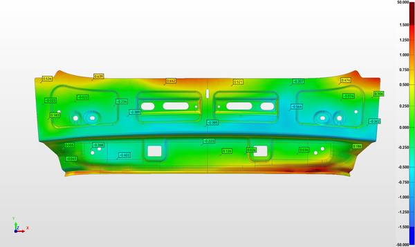
Batch inspection and statistical process control. When measuring multiple identical parts against a CAD model, target-assisted alignment ensures that each scan registers to the same coordinate system consistently. This repeatability is essential for generating meaningful deviation maps and tracking process drift over time.
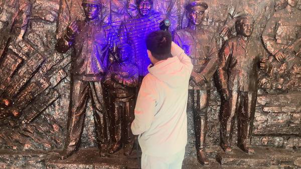
On-site work in confined spaces. In field service or in-situ inspection of large assemblies, operators often cannot walk around a part freely. Placing targets in visible locations allows the scanner to maintain alignment even when the scanning path is constrained.
Conversely, if a part is small, has abundant sharp features, and does not require batch-to-batch comparison, feature-only alignment may be faster and perfectly adequate. The key is to match the method to the measurement task, not to default to one approach.
Practical Selection Criteria for 3D Scan Targets
Engineers evaluating whether to incorporate targets into a handheld scanning workflow should weigh several factors.
- Part geometry and surface condition. Are there enough distinct features for reliable feature-based alignment? If the answer is uncertain, running a quick test scan without targets often reveals alignment weaknesses within minutes.
- Required measurement uncertainty. Tighter tolerances demand more robust alignment. If the allowable error is a fraction of the scanner’s stated accuracy, targets become a prudent safeguard.
- Production volume and mix. High-mix, low-volume environments benefit from the flexibility of targets over dedicated fixtures. High-volume lines may justify custom fixturing if cycle time is the dominant concern.
- Target type and placement. Target diameter should match the working distance. Larger targets are easier to detect at range but cover more of the part surface, reducing measurement point density in those areas. Magnetic or rigid target arrays work well for permanent workbench setups; adhesive targets suit one-off jobs. Placement should span multiple planes and avoid tight clusters to strengthen the bundle adjustment solution.
- Environmental conditions. If the part or targets will experience temperature changes during scanning, thermal drift can introduce systematic error. Using targets with low thermal expansion and allowing the part to stabilize before scanning mitigates this risk.
How INSVISION AlphaScan Implements 3D Scan Target Detection
INSVISION’s AlphaScan handheld scanner family integrates target detection as a core metrology function, not an afterthought. The system uses retroreflective targets whose spectral response is tuned to the scanner’s 450 nm blue laser, maximizing the signal-to-noise ratio during capture. Dimensional tolerances on the targets are controlled to support the scanner’s 0.020 mm stable accuracy specification.
The onboard AI+3D algorithm filters target returns in real time. Rather than flagging every bright reflection, it evaluates spatial consistency, return intensity profile, and geometric fit to reject false positives from ambient metallic surfaces or coolant residue.
This filtering operates reliably across the scanner’s full -10 °C to 40 °C operating range, which matters during extended scans of large aerospace structures or automotive injection molds where ambient conditions can shift.
AlphaScan’s software supports both target-assisted and feature-only alignment within the same project. An operator can place targets on challenging areas of a part while letting feature-based alignment handle well-defined regions. The software also accepts photogrammetry scale bar data, so teams can combine coded targets and scale bars for multi-meter assemblies that require a global coordinate reference.
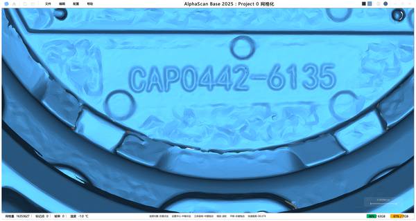
All mainstream 3D data formats are supported, allowing scan data to flow directly into existing digital thread workflows—CAD comparison, GD&T reporting, reverse engineering, and archival.
Common Questions About 3D Scan Targets
Do I need 3D scan targets for every handheld scanning project?
No. Targets deliver the most value when projects demand stable global alignment across large volumes, repeatable batch scanning, or scanning of low-feature or high-reflectivity surfaces. For parts with adequate geometric texture and moderate size, feature-based alignment often suffices. INSVISION’s AlphaScan lets operators switch between modes based on the job.
What type of targets work with metrology-grade handheld scanners?
Metrology-grade scanners perform best with standardized retroreflective targets that have tight dimensional tolerances and spectral response matched to the scanner’s laser wavelength. For AlphaScan, that means targets optimized for 450 nm blue laser detection. Magnetic or rigid target arrays are useful for permanent workbench setups; adhesive targets suit one-off or field work.
How does target placement affect accuracy?
Placement geometry is critical. Targets distributed across multiple planes with good angular diversity produce stronger bundle adjustment results than targets clustered in a small area. Poor placement can degrade accuracy even if the targets themselves are high quality.
Can I use 3D scan targets on shiny or dark surfaces?
Yes. Because targets are retroreflective, they create high-contrast reference points that the scanner can detect regardless of the underlying surface finish. This is one of the primary reasons to use targets on high-gloss molds or dark composite parts where feature-based alignment struggles.
What are the main accuracy limitations when using targets?
Beyond placement geometry, thermal drift during long scanning sessions can introduce systematic error if the workpiece or targets expand or contract. Using targets with stable material properties and allowing temperature equilibration before scanning helps control this effect. Additionally, target diameter must be appropriate for the working distance; a target that is too small may not be detected reliably at range.
Summary
3D scan targets are a metrology tool, not a magic bullet. They solve a specific problem—accumulated alignment drift in multi-pose handheld scanning—by providing invariant reference points that tie all scans into a common coordinate system. Their effectiveness depends on spectral matching, dimensional stability, intelligent filtering, and thoughtful placement.
For engineers and quality managers, the decision to use targets should be driven by part geometry, tolerance requirements, and production context. INSVISION’s AlphaScan platform offers a flexible implementation that supports both target-assisted and feature-only workflows, allowing teams to apply the right alignment strategy to each measurement task without changing equipment.
In an industrial landscape where measurement confidence directly affects downstream decisions, that flexibility is a practical advantage.
Hangzhou Insvision Technology Co.,Ltd.
Address: Building 1, No. 1399 Liangmu Road, Yuhang District, Hangzhou, Zhejiang 311121, China