

What a Coordinate Measuring Machine Can’t See: The Case for 3D Inspection of Mechanical Components
A machined impeller sits on a granite surface plate. The quality engineer needs to verify blade profile tolerance, wall thickness distribution, and the concentr
The challenge is not limited to exotic alloys or rotating equipment. Mechanical components arrive in inspection bays with a wide range of surface conditions that can confound optical systems. A cast aluminum pump housing may have a matte, as-cast finish that scatters structured light unevenly.
A ground gear shaft may have polished bearing journals that reflect the projector pattern straight back into the sensor, creating data voids. A black anodized pneumatic manifold can absorb enough light to defeat a scanner that was calibrated for neutral-gray surfaces. The operator needs a system that adapts to these conditions without requiring a full coat of developer spray on every part.
Deployment Validation Checklist
| Focus Area | Decision Point | Deployment Note |
|---|---|---|
| Target part | Check size, surface condition, and key tolerances against the scan task | Run a full trial scan on a representative part |
| Data workflow | Verify point cloud, deviation map, and quality-report handoff | Confirm export formats and review ownership in advance |
| Shop-floor use | Review training, calibration, lighting, and working space | Keep the validation record as a repeatable inspection reference |
The handheld approach matters here because the technician can tilt the scanner relative to the surface, finding the working angle that returns usable fringe data even on shiny or dark substrates.
What makes this practical in a production environment is the combination of blue laser or structured light projection with on-board exposure control that adjusts frame-by-frame, keeping scan data dense even when the surface finish changes mid-part.
The Object Profile: What Makes a Mechanical Component Difficult to Digitize
Every mechanical component brings a specific set of inspection obstacles. The material itself is the first variable. Forged steel parts with heat-treat scale present a diffuse surface that scans easily, but the same part after finish grinding becomes mirror-like and demands careful angle management.
Aluminum castings introduce porosity and flash that generate noise if the scan resolution cannot distinguish real geometry from surface texture. Thin-walled components, such as sheet metal brackets or welded assemblies, can deflect under their own weight or under the clamping force of a fixture, meaning the part must be scanned in a free-state condition that reflects how it actually functions in the assembly.
Deep bores, blind tapped holes, and internal threads in valve bodies or hydraulic manifolds create line-of-sight dead zones that no single scan position can resolve. The operator must build a scan strategy that sequences multiple approach angles, and the software must stitch those segments into a coherent point cloud without accumulating registration error across the loop.
Size and thermal stability also shape the inspection approach. A large weldment that spans a meter or more will expand measurably between a cold morning shift and an afternoon measurement if the shop floor temperature is not controlled. The scan data captures the part at a specific thermal state, and the alignment to CAD must account for the reference temperature at which the model was defined.
Smaller parts, particularly those with tight tolerances in the IT6 to IT7 range, require a scanner with proven volumetric accuracy and a calibration routine that can be verified with a traceable artifact before the measurement session begins.
INSVISION addresses this through its AlphaScan handheld 3D scanner, which is designed to maintain metrology-grade stability across the working volume without requiring a warm-up sequence that interrupts the workflow.
Scan Strategy: From First Light to Complete Mesh
The inspection sequence begins with part preparation, but the goal is to minimize it. A typical approach for mechanical components involves placing a small number of adhesive reference targets on non-critical surfaces or on the fixture plate itself. The targets define a local coordinate frame that the scanner tracks in real time, allowing the operator to move the part or the scanner freely without losing alignment.
For components that cannot be marked, such as sealing faces or bearing surfaces, the targets can be placed on a jig that holds the part in a repeatable orientation.
The scan path follows the geometry. The operator starts on a large, feature-rich face to establish a stable reference cloud, then works around the part, tilting the AlphaScan into pockets and flanges. The scanner’s projection pattern and depth of field determine how close the device must be held to the surface.
For a gearbox housing, the scan path might move from the mounting flange face, across the bearing bores, into the internal ribbing, and then out to the external bosses. The software displays the live point cloud with a color map showing data density, so the operator can see immediately if a critical feature has been under-sampled.
If a bore is partially occluded, the operator can take a second pass at a different angle without restarting the scan. The point cloud grows incrementally, and the registration algorithm aligns each new frame to the existing data using the target geometry and the surface features themselves.
The raw output is a dense triangular mesh, typically in the range of millions to tens of millions of polygons depending on the part size and resolution setting. For a mechanical component in the 200 mm to 500 mm size range, a scan session might take four to eight minutes of active scanning, plus setup time.
The mesh is then cleaned to remove obvious outliers, the scaffold geometry from the fixture, and any data on surfaces that are not part of the inspection scope. At this stage, the file is ready for comparison to the nominal CAD model.
Data Pipeline: Alignment, Colormap, and the Report That Matters
The transition from scan data to actionable inspection report is where the value of 3D inspection of mechanical components is either realized or lost. The mesh is imported into the metrology software alongside the CAD model. The first step is a best-fit alignment that minimizes the overall deviation between the scanned data and the nominal geometry.
For components where specific datums control the assembly interface, the alignment can be constrained to those datum features: a primary plane, a secondary cylinder, and a tertiary point, exactly as defined on the drawing. This is not a cosmetic choice; it determines whether the measured deviations reflect what matters in the assembly.
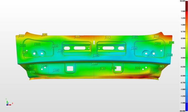
Once aligned, the software computes a surface comparison and renders it as a color deviation map. The engineer can see at a glance where the part is within tolerance, where it is approaching the limit, and where it is out of spec. A cast pump volute might show positive deviation on the outer curvature due to core shift, while the machined mounting face is flat within 0.02 mm.
The AlphaScan workflow, when paired with INSVISION’s inspection software, supports direct CAD overlay and GD&T annotation, so the colormap is not just a qualitative picture but a quantitative measurement tied to the feature control frames on the print.
Wall thickness analysis can be run by computing the distance between the external mesh and the internal surface, which is critical for thin-walled castings and additively manufactured components.
The inspection report must be self-contained and traceable. It includes the part identification, the scan parameters, the alignment method, the date and time, the operator name, and the full deviation results for each inspected feature. The report can be exported as a PDF for the quality record and the raw data can be archived for trend analysis.
If a part is out of tolerance, the report provides the evidence needed to adjust the machining offsets, rework the tooling, or quarantine the batch. The digital thread does not end with the report; the same scan data can be used for reverse engineering if the design intent was never captured in CAD, or for wear analysis if the component is a service return being compared to its as-manufactured state.
Applying the Workflow Across Different Mechanical Components
The same scan-to-report methodology adapts across a wide range of mechanical parts, but the inspection priorities shift. For a machined hydraulic manifold, the focus is on port positions, thread quality, and the flatness of the sealing surfaces. The scan data must resolve small features with high edge definition, and the alignment must be driven by the manifold’s mounting holes.
For a stamped and welded bracket, the priority is springback analysis: comparing the formed part to the CAD model to quantify how much the material has relaxed after the stamping operation. Here the scan captures the free-state shape, and the deviation map reveals the twisting and bending that are invisible to a hard gauge.
For a turbine blade, the critical measurements are the leading and trailing edge profiles, the chord length, and the cross-sectional area at multiple spanwise positions. The AlphaScan can capture the airfoil geometry in a single scan session, and the software can extract the 2D profiles at specified planes for overlay comparison to the nominal airfoil.
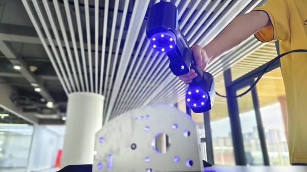
The AlphaScan handheld 3D scanner from INSVISION fits into this workflow as a tool that can be moved around the part, operated on the shop floor or in the quality lab, and relied upon to produce repeatable results across shifts and operators. The output is not just a point cloud, but a measurement record that connects the physical part to the digital definition and closes the loop between manufacturing and design.
Hangzhou Insvision Technology Co.,Ltd.
Address: Building 1, No. 1399 Liangmu Road, Yuhang District, Hangzhou, Zhejiang 311121, China