

From Black Plastic to Polished Steel: A Part-Centric Strategy for 3D Inspection of Industrial Parts
## Understanding the Part Before the First Scan: Materials, Coatings, and Geometric Complexity Industrial parts do not arrive at the inspection station with a n
Understanding the Part Before the First Scan: Materials, Coatings, and Geometric Complexity
Industrial parts do not arrive at the inspection station with a neat label describing their ideal measurement strategy. A single production batch can include sand-cast aluminum housings with rough, dark oxide skins, precision-machined steel brackets with mirror-like polished surfaces, and injection-molded connectors made of high-gloss black nylon.
Each material and surface type introduces a distinct optical behavior that directly affects data quality. A glossy steel surface can produce laser speckle that confuses triangulation sensors, while a deeply colored plastic may absorb so much light that the scanner struggles to return enough signal.
Beyond material properties, the geometry itself presents a puzzle: thin-walled sections that flex under contact probe pressure, deep bores with diameters under ten millimeters, intersecting fillets and blend radii that are difficult to define with a few touch points, and fine mesh structures where every gram of weight matters.
Deployment Validation Checklist
| Focus Area | Decision Point | Deployment Note |
|---|---|---|
| Target part | Check size, surface condition, and key tolerances against the scan task | Run a full trial scan on a representative part |
| Data workflow | Verify point cloud, deviation map, and quality-report handoff | Confirm export formats and review ownership in advance |
| Shop-floor use | Review training, calibration, lighting, and working space | Keep the validation record as a repeatable inspection reference |
A 3D inspection workflow that does not start with a thorough reading of the part will quickly generate hours of rework and questionable data.
Key Points at a Glance
- Industrial parts do not arrive at the inspection station with a neat label describing their ideal measurement strategy.
- Mirror finishes and translucent polymers are not edge cases;
- A productive scan routine begins with a feature map of the part: identify datum surfaces, locate the areas where form tolerances are tight, and…
The challenge intensifies when manufacturing tolerances fall into the tens of microns. A diesel engine bracket might require true position checks on several dowel holes, profile tolerances on sealing faces, and wall thickness verification in narrow channels. Relying on traditional tactile probing for such features means accepting a compromise between point density and cycle time.
A coordinate measuring machine can gather a few dozen reference points per feature, but it cannot fully characterize a warped gasket face or a gradually varying draft angle across a die-cast rib. This is where the scanning strategy must shift from linear touch-trigger inspection to full-field surface capture, and why the choice of 3D scanning hardware becomes inseparable from the physical characteristics of the part itself.
Where Conventional Inspection Stalls: Surface Effects, Access, and Deformation Risks
Mirror finishes and translucent polymers are not edge cases; they are everyday realities in automotive, medical device, and consumer electronics manufacturing. A polished valve seat or a clear polycarbonate housing can make a standard laser scanner unusable without a temporary matting spray, which adds cleanup time, risk of residue, and process variability.
When the part is small and delicate, such as a hearing aid shell or a microfluidic chip, any contact measurement method risks deforming the article and invalidating the reading. Parts with deep, narrow cavities present another category of difficulty: the sensor must see into a recess where the line-of-sight angle is steep and the bottom is often shadowed by the rim.
A fixed scanner or a CMM probe head may simply not reach the critical surfaces, leaving the inspection operator to make judgment calls based on partial data.
Cycle time pressure compounds these issues. In a contract machining shop, a family of pump housings might arrive in lots of fifty, each requiring first-article inspection, process capability studies, and a final report for the customer. Waiting for a CMM program to complete a full contour scan on every part can stall the entire production line.
The practical answer is a handheld 3D scanning approach that can be moved around the part, capturing data from multiple angles and stitching the scans into a cohesive model. However, not all handheld scanners handle the material variety well.
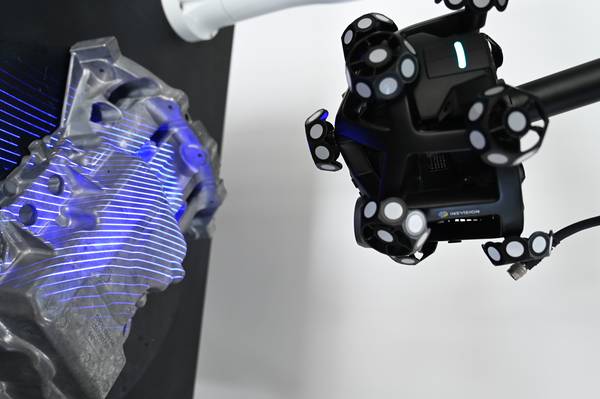
The INSVISION AlphaScan, built around blue laser technology and AI-driven exposure control, adjusts its acquisition parameters dynamically so that the same scan head can capture dark carbon-fiber brackets, oxidized cast iron, and brushed aluminum without repeated recalibration or operator intervention.
This ability to keep the scanning workflow continuous across material changes reduces the temptation to cut corners and miss critical features.
Designing a Scan Routine That Follows the Part’s Logic
A productive scan routine begins with a feature map of the part: identify datum surfaces, locate the areas where form tolerances are tight, and mark the zones that are prone to thermal distortion or tool wear.
For a complex part like a motorcycle engine cover that combines a large sealing face, bearing bores, and thin cooling fins, the operator might start with a few wide-angle passes around the outer contour to establish a stable reference frame, then move into targeted high-resolution scans of the gasket groove and the bearing seat.
The AlphaScan handheld scanner supports feature-based alignment and can use the part’s own geometry — planes, cylinders, and freeform surfaces — to lock the scan data into a consistent coordinate system without needing to attach targets to every piece. This is vital when measuring parts that will be machined on the back side later, where the raw casting surface provides the only stable reference.
During the scan, the user can watch the live point cloud build on
Hangzhou Insvision Technology Co.,Ltd.
Address: Building 1, No. 1399 Liangmu Road, Yuhang District, Hangzhou, Zhejiang 311121, China