

How to Scan 3D scanning for complex freeform surfaces Without Losing Inspection Detail
The geometry of a turbine blade does not follow a straight line. Neither does a cast intake manifold, a stamped body panel, or a custom prosthetic socket. These
What Makes Freeform Surfaces Difficult to Quantify
The difficulty starts with material and finish. Many freeform parts are cast, forged, injection-molded, or machined to a near-net shape and then finished with coatings, textures, or polishing. A shiny aluminum intake port reflects light unevenly. A dark carbon-fiber layup absorbs laser energy.
A transparent acrylic medical device component is nearly invisible to structured-light scanners unless prepared with a temporary matte coating. Beyond material, there is the question of feature scarcity. A sculpted surface may have no flat datum, no sharp edge, and no drilled hole to serve as a reference. The inspector cannot simply align the part to a CAD model using three planes and two circles.
The alignment itself becomes a mathematical optimization that must distribute error across the entire surface.
Deployment Validation Checklist
| Focus Area | Decision Point | Deployment Note |
|---|---|---|
| Target part | Check size, surface condition, and key tolerances against the scan task | Run a full trial scan on a representative part |
| Data workflow | Verify point cloud, deviation map, and quality-report handoff | Confirm export formats and review ownership in advance |
| Shop-floor use | Review training, calibration, lighting, and working space | Keep the validation record as a repeatable inspection reference |
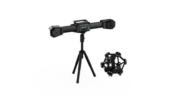
Scenario Snapshot
A practical way to read the article is through this scenario:
- What Makes Freeform Surfaces Difficult to Quantify: The difficulty starts with material and finish.
- Building a Scan Strategy Around the Object: A useful scan of a freeform surface begins with object analysis, not with the scanner.
- From Point Cloud to Pass/Fail Decision: Once the full surface is captured, the data stream moves into a processing pipeline that is as important as the sc…
Size and flexibility introduce further complications. A large thermoformed panel may sag under its own weight. A thin-walled impeller blade can deflect by tens of microns under finger pressure. Clamping such a part for measurement changes its shape. The act of measurement alters the result. Deep cavities and occluded regions compound the issue.
The area behind a blade root or inside a volute housing is often unreachable by a single scan angle. The object must be scanned in multiple orientations, and the data sets must be registered together without introducing layer shift. In all these cases, the challenge is not that a scanner cannot see the surface.
The challenge is that the surface behaves more like a living shape than a rigid prismatic block, and the measurement process must account for that behavior.
Building a Scan Strategy Around the Object
A useful scan of a freeform surface begins with object analysis, not with the scanner. The operator must map out zones of high curvature, identify regions where the surface transitions rapidly, and note any areas where reflections or occlusions are likely. For a cast turbocharger housing, the internal volute passage is the functional zone of interest. The outer flange faces are secondary.
The scan strategy prioritizes the volute. The operator positions the part with the inlet facing upward, uses a handheld scanner to sweep the internal passage in a spiral motion, and then captures the flange faces in a second registration loop.
The two datasets are aligned using the part’s own geometry, often through a global-best-fit algorithm that minimizes deviation across overlapping regions rather than relying on a single reference feature.
Color and reflectivity are managed through exposure control and, where necessary, a thin layer of scanning spray. The goal is not to remove all shine but to reduce the dynamic range of reflected light so the sensor can maintain a consistent point density. Some scanners, including the AlphaScan handheld system from INSVISION, adjust laser intensity and camera exposure on the fly, frame by frame, based on the surface response.
This is particularly useful when scanning a part that transitions from a blasted texture to a polished surface within a single component. The operator does not need to stop, adjust settings, and restart. The scanner adapts. For parts with deep pockets or narrow slots, the scan path includes deliberate overlap, approaching the cavity from two or three different angles to ensure that the bottom and side walls are fully captured.
The resulting point cloud is inspected in real time on the display, and any low-density patches are rescanned immediately before the part leaves the fixture.
From Point Cloud to Pass/Fail Decision
Once the full surface is captured, the data stream moves into a processing pipeline that is as important as the scan hardware. The raw point cloud is cleaned—spurious points from fixture edges or dust are removed. The remaining data is triangulated into a mesh. This mesh is the digital twin of the as-built part.
The mesh is then aligned to the nominal CAD model typically using a best-fit alignment that minimizes the root-mean-square error across the entire surface. For freeform parts, this global alignment is often more revealing than a feature-based alignment because it shows where the overall shape deviates from the design intent, not just where a few critical points are off.
The comparison produces a color map: a gradient overlay that shows deviation at every point on the surface. Blue zones indicate material that is below the nominal surface. Red zones indicate excess material. Green zones are within tolerance. A design engineer looking at a turbine blade color map can immediately see that the leading edge is consistently thick by 0.12 mm while the trailing edge is within spec.
This is not a number buried in a spreadsheet. It is a visual story of how the manufacturing process—perhaps a wax pattern that distorts during investment casting—affects the final shape. The inspection report can include sections, point deviations, GD&T annotations, and statistical summaries for the entire production batch.
When the AlphaScan workflow is integrated into a quality lab, the scan data is archived with traceability to the part serial number, and subsequent scans of the same part family can be compared against the same baseline. The report becomes a living document, not a one-time snapshot.
Where the Workflow Fits and What to Validate Before Buying
Freeform surface scanning is not a single application. It spans industries from automotive powertrain casting to medical implant manufacturing, from consumer product design to aerospace blade repair. The common thread is this: the part has a shape that cannot be described by a drawing with a few linear dimensions, and the cost of getting that shape wrong is high.
In those scenarios, the value of full-field 3D scanning is not just speed. It is the ability to see the entire surface and to catch deviations that point measurements would miss entirely.
Teams evaluating a handheld scanner for freeform work should focus on a few practical factors. Scanner accuracy specification should be verified against a traceable artifact, ideally under conditions that match the shop floor—not just a climate-controlled lab. The scanner’s behavior on dark, shiny, or mixed-finish surfaces should be tested on the team’s own parts, not only on the manufacturer’s demo samples.
The software workflow for alignment and reporting should be walked through from start to finish with a real part file, because the quality of the color map and the flexibility of the alignment tools determine whether the scan data translates into actionable information.
INSVISION’s AlphaScan, built around a metrology-grade optical engine and tested against CNAS and PTB standards, is designed for this kind of heterogeneous surface environment. Its on-the-fly exposure management and robust registration are especially relevant when scanning freeform parts that resist simple fixture-based measurement. The last thing to check is how the scanner handles repeatability across operators.
A freeform surface scan is only as good as its consistency, and a system that delivers the same result from three different users on three different shifts is the one that earns its place in a production quality loop.
Hangzhou Insvision Technology Co.,Ltd.
Address: Building 1, No. 1399 Liangmu Road, Yuhang District, Hangzhou, Zhejiang 311121, China