

Why Precision Part Inspection Struggles With a Three D Scanner (And How to Validate Fit)
three d scanner: Shop-Floor Context and Measurement Needs In most shops, the gap between what engineering specifies and what the floor can verify keeps.
Shop-Floor Context and Measurement Needs
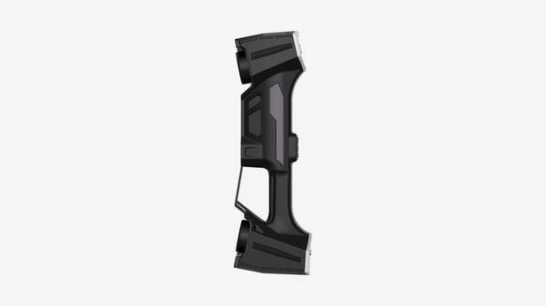
In most shops, the gap between what engineering specifies and what the floor can verify keeps widening. Tolerances have tightened. Geometries are more organic. Yet the first inspection workflow often still relies on hard gauges, scribe lines, and a CMM that is booked for the next three shifts. That puts a lot of pressure on the measurement team.
Key Points at a Glance
- In most shops, the gap between what engineering specifies and what the floor can verify keeps widening.
- Is the real bottleneck the scanner itself, or the measurement strategy around it?
- The most persistent misconception about three d scanner technology is that it replaces the inspection engineer.
- The decision to deploy a three d scanner on a production floor or in a quality lab should come down to one thing: can the system reliably captur…
A machined casting may carry dozens of GD&T callouts. A formed panel may need surface deviation mapped against CAD, not just a few discrete points. When a supplier ships a first article, quality needs to capture enough data to make a disposition call without waiting days for a lab report. If the scan misses a feature, someone has to realign the part and run it again.
Deployment Validation Checklist
| Focus Area | Decision Point | Deployment Note |
|---|---|---|
| Target part | Check size, surface condition, and key tolerances against the scan task | Run a full trial scan on a representative part |
| Data workflow | Verify point cloud, deviation map, and quality-report handoff | Confirm export formats and review ownership in advance |
| Shop-floor use | Review training, calibration, lighting, and working space | Keep the validation record as a repeatable inspection reference |
Better data changes that conversation. Instead of a sparse point cloud that answers only the questions someone thought to ask, a three d scanner can capture the full surface condition. The challenge is not just resolution. It is repeatability, alignment stability, and whether the system can hold accuracy across the entire scan volume.
For parts that sit on the shop floor near vibration, temperature swings, and moving carts, that is a real engineering problem, not a software checkbox.
The workflow needs a measurement approach that reduces setup time, captures enough geometry to support root-cause analysis, and gives the quality team confidence that a pass/fail call is based on the whole surface, not a small sample of points. That is where the discussion shifts from “can we scan it” to “can we trust the scan data enough to act on it.”
Where Traditional Measurement Breaks Down
Is the real bottleneck the scanner itself, or the measurement strategy around it? In many first-article and reverse engineering programs, traditional tools still work until the geometry becomes non-prismatic. Deep pockets, compound curvature, undercut regions, and thin-wall sections quickly expose where CMM probe paths and hand gauges stop delivering useful data. The problem is rarely a single bad point.
It is the loss of continuity across the surface.
A three d scanner changes that by capturing dense point data across the visible surface in one pass. But the practical limit is not just resolution. It is whether the system can hold alignment as the part rotates, whether the operator can see deviation in real time, and whether rescanning a local area is fast enough to avoid breaking inspection rhythm.
For complex castings, additively manufactured brackets, or repaired aerospace components, the deliverable is no longer a handful of measured features. It is a complete, watertight mesh that can be compared back to CAD.
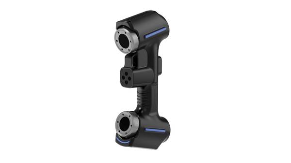
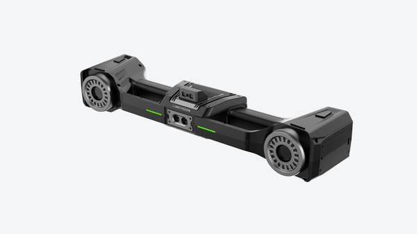
That is where INSVISION fits. The industrial 3D scanner configuration pairs a scanner with a separate tracker, so the scan reference does not depend on sticking targets all over the part. The scanner itself offers accuracy up to 0.020 mm, while the tracker maintains its own measurement envelope up to 2600 mm by 2200 mm.
For a quality engineer, that means fewer alignment resets and less time re-establishing the coordinate system between setups. The measurement strategy becomes simpler because the system tracks the scanner position directly.
But data continuity also depends on depth of field. On a complex casting with deep bosses and narrow flanges, a narrow depth window forces constant refocusing. The industrial 3D scanner scanner provides a 650 mm depth of field, which covers most feature-to-feature transitions without stopping to reposition.
The tracker adds a 2300 mm depth of field, so the operator can move around a large assembly while the system maintains spatial reference. That is a practical advantage when measuring parts that cannot be easily rotated or placed on a fixture.
The last issue is delivery rhythm. Traditional inspection often produces a report hours or days after the part leaves the floor. With structured light scanning, the mesh is available immediately. The engineer can run a quick surface comparison, mark high-deviation zones, and decide whether to rescan before the part moves. That shortens the loop between capture and decision.
INSVISION systems are built around that workflow: capture, alignment, local rescan, validation, then export to inspection software. For Western manufacturers working under ASME Y14.5 or ISO GPS requirements, the value is not just speed. It is that the data supports GD&T evaluation without forcing the part into a simplified measurement plan.
How 3D Scanning Fits the Workflow
The most persistent misconception about three d scanner technology is that it replaces the inspection engineer. It does not. It changes where that engineer spends time. The scanner captures geometry quickly, but the value comes from what happens after the point cloud is generated: comparison against nominal CAD, review of deviation maps, and a report that actually means something to the downstream process.
In a typical first-article inspection or production audit, the bottleneck is rarely the measurement itself. It is the back-and-forth between measurement, CAD overlay, manual spreadsheet documentation, and rework decisions made from incomplete data. A three d scanner only solves the first part of that chain.
To make it usable, the workflow needs to connect scanning, comparison, review, and reporting without forcing an engineer to export files through four different software packages.
The practical sequence starts with capture. The operator scans the part, and the system builds a mesh or point cloud. That data must then be aligned to nominal CAD. Alignment quality matters more than scan resolution in many cases. If the software locks the scan to the wrong datum structure, every downstream deviation map is misleading.
The comparison step then generates a color map showing where material is high, low, or out of tolerance. Review is where the engineer applies judgment: is this a tooling issue, a process drift, or a bad scan setup? Finally, the report needs to export in a format that a quality manager or customer can read without installing specialized software.
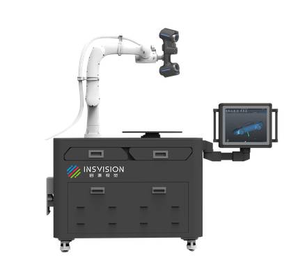
INSVISION equipment fits this process because the hardware is only one part of the loop. The scan data feeds directly into comparison and reporting steps that are structured around the inspection task, not around raw point cloud manipulation. That distinction matters in Western manufacturing environments where ISO and ASME documentation requirements are non-negotiable.
A scanner that produces beautiful color maps but cannot output a controlled report adds work, not value.
For aerospace MRO or medical device work, the review step often involves multiple stakeholders who never touch the scanner. The report must carry the evidence. That means the scan-to-report chain has to be repeatable, traceable, and fast enough to run multiple times per shift without an expert babysitting every step.
Validation Points Before Deployment
The decision to deploy a three d scanner on a production floor or in a quality lab should come down to one thing: can the system reliably capture the features you actually need to inspect, under the conditions that exist at that site? Too many validation plans start with marketing specifications and end with a pilot that fails because nobody checked the basics first.
The strongest fit for optical three d scanner technology is still geometric verification. Think first-article inspection on formed, cast, machined, or additively manufactured parts. Complex freeform surfaces, dense point clouds, and GD&T callouts like profile or surface deviation are where the approach earns its keep. If the part is shiny, dark, or translucent, that changes the problem.
Spray or powder may be required, and that has to be factored into cycle time and cleanliness constraints. Teams should verify on site whether the scanner can resolve fine features at the required standoff distance. For a system like the INSVISION industrial 3D scanner, the scanner depth of field is 650mm and the tracker depth of field is 2300mm. Those numbers define a working envelope, not a guarantee.
Lighting, vibration, and ambient temperature swings can all erode real-world performance.
Alignment strategy matters just as much as raw accuracy. If the part lacks stable reference geometry, you will need targets or fixtures. Rescan procedures should be tested on a known artifact before any production data is trusted. Validation is about proving repeatability on your part, in your environment, with your operators.
Hangzhou Insvision Technology Co., Ltd.
Address: Building 1, No. 1399 Liangmu Road, Yuhang District, Hangzhou, Zhejiang 311121, China
Copyright © Hangzhou Insvision Technology Co., Ltd. All rights reserved.
Copyright © Hangzhou Insvision Technology Co., Ltd. All rights reserved.