

What to Validate First When Choosing a 3D Scanner for Automotive Quality
3d scanner automotive: Who This Guide Is For: Automotive Quality Teams Facing 3D Scanning Purchase Decisions Who This Guide Is For: Automotive Quality Teams.
Who This Guide Is For: Automotive Quality Teams Facing 3D Scanning Purchase Decisions
If you are the person who gets called when a first-article inspection stalls, a gage R&R study shows unacceptable variation, or a tier-one customer rejects a PPAP submission because the CMM report does not align with the physical part, this section is written for you.
Deployment Validation Checklist
| Focus Area | Decision Point | Deployment Note |
|---|---|---|
| Target part | Check size, surface condition, and key tolerances against the scan task | Run a full trial scan on a representative part |
| Data workflow | Verify point cloud, deviation map, and quality-report handoff | Confirm export formats and review ownership in advance |
| Shop-floor use | Review training, calibration, lighting, and working space | Keep the validation record as a repeatable inspection reference |
The readers we keep in mind here are quality engineers, IATF 16949 compliance leads, production managers, and procurement specialists at North American and European automotive OEMs, tier-one suppliers, and tier-two machining or molding operations. You are not shopping for a scanner because it looks interesting.
You are shopping because the current measurement workflow is not keeping up with the parts, the tolerances, or the delivery schedule.
The decision in front of you is bigger than a specification sheet. You are selecting a 3D scanning solution that has to support three different jobs at once: dimensional inspection against GD&T callouts, reverse engineering of legacy or modified components, and long-term process improvement on the shop floor. If the scanner works only in a lab, it will fail where you need it most.
If it requires a dedicated operator with specialized programming knowledge, it will sit idle when that person is out. If it cannot handle the surface finish of stamped, cast, or machined automotive parts without excessive prep, it will not survive first contact with your actual production line.
The most common costly misjudgment we see is this: a team narrows the purchase to advertised accuracy specifications, often a single number printed on a brochure, and never tests the scanner against the real parts that have caused past quality escapes.
Accuracy specs matter, but they are only meaningful when they hold up on a production part with oil residue, vibration, mixed surface finishes, and a technician who has been on shift for seven hours. A scanner that performs well on a matte ceramic reference artifact can struggle on a shiny machined sealing face or a dark molded bracket. The advertised number does not tell you that. The validation test does.
The goal of this guide is to give you a practical way to evaluate 3D scanner automotive options without falling into that trap. We will walk through a validation framework that forces the scanner to prove itself on your parts, not the supplier’s demo parts. We will cover use case fit guidance so you can distinguish between a scanner suited for in-line trend monitoring and one better matched to offline reverse engineering.
We will also provide a de-risking checklist that covers the operational questions procurement teams often miss: training time, fixture requirements, software export compatibility with your existing SPC or CAD platform, and what happens when the scanner needs service.
INSVISION builds industrial 3D scanning systems used in automotive inspection and reverse engineering workflows. Throughout this article, the focus stays on the evaluation logic, not on pushing a particular model. If a scanner cannot pass the validation steps described here, the brand name on the housing does not matter. If it passes, you will have the evidence your quality team and your finance team both need to move forward.
Three questions should frame the rest of this guide. First, can the scanner measure the specific features that have caused your recent quality issues, including deep pockets, narrow slots, or edges with tight profile tolerances? Second, can your existing staff operate it after reasonable training, or does it create a new single point of failure?
Third, does the data output integrate with the reports and analysis tools you already use, or does it create a parallel process that duplicates work? Answer those three questions with evidence from your own parts, and the purchase decision becomes much less risky.
The next sections break this down into a repeatable process. You will see how to define your measurement requirements before looking at any scanner, how to structure a realistic on-site or in-lab validation, and how to compare the operational costs of keeping your current workflow versus adding a 3D scanning system. No supplier rankings, no inflated ROI claims.
Just the criteria that separate a scanner that solves your problem from one that creates a new one.
Hidden Operational Costs of Traditional Automotive Inspection That Undermine Lean Goals
For a quality lead evaluating inspection workflows, the decision rarely hinges on whether a part meets a tolerance in isolation. It hinges on what happens when the first-article check stalls, the CMM queue backs up, and a batch waits while one skilled metrology technician works through a fixture setup. That is where traditional automotive inspection quietly erodes lean targets.
Manual caliper checks and fixed CMM routines create bottlenecks that delay first-article approval and batch release. Overreliance on a few experienced metrology staff introduces scheduling risk and knowledge gaps when those individuals are unavailable. Defects that escape initial manual sampling surface later as rework or scrap, consuming material and capacity that could have gone to conforming output.
Handwritten or siloed measurement records complicate IATF 16949 traceability during audits, forcing quality teams to reconstruct evidence under time pressure. Many Western plants now explore a 3D scanner automotive workflow as a practical response.
INSVISION supports this shift with industrial 3D scanning tools that capture full surface data faster than point-based checks, reduce dependence on manual setup, and generate digital records that fit existing quality documentation. The operational value is straightforward: shorter inspection cycles, earlier defect visibility, and traceable data without added administrative burden.
Scenario Snapshot
A practical way to read the article is through this scenario:
- Hidden Operational Costs of Traditional Automotive…: For a quality lead evaluating inspection workflows, the decision rarely hinges on whether a part meets a tolerance…
- 5 Non-Negotiable Validation Criteria for Automotive…: If you are evaluating a 3D scanner for automotive inspection, start with the workpiece, not the spec sheet.
- How INSVISION 3D Scans Align With Automotive Qualit…: How do you verify stamped components, powertrain parts, or chassis geometry without letting inspection become the…
5 Non-Negotiable Validation Criteria for Automotive 3D Scanner Selection
If you are evaluating a 3D scanner for automotive inspection, start with the workpiece, not the spec sheet. A stamped body panel, a machined steering knuckle, and a reflective transmission housing place very different demands on the same tool. The most common misjudgment is buying for peak accuracy while ignoring how the scanner behaves on an oily, vibration-prone shop floor at production cadence.
Weight each criterion to your own part mix and line rhythm. Do not rely on generic benchmarks.
- Part and Surface Compatibility
Large stamped assemblies require a wide scanning area and enough depth of field to capture deep draws without constant repositioning. Small powertrain components demand tight feature resolution. Reflective or machined surfaces are the real test: if the scanner struggles without heavy powder coating, inspection time and labor climb quickly.
Validation question: Can one setup capture both a large panel and a small precision part without switching lenses or recalibrating?
- Inspection Speed Matched to Production Cadence
Speed only matters in context. Batch sampling tolerates slower data acquisition; high-volume line checks do not. A scanner that creates a bottleneck at the quality station erases its own value, no matter how accurate it is.
Validation question: Does the scan-plus-analysis cycle fit the takt time for both first-article inspection and in-process sampling?
- Accuracy Matched to Automotive Tolerance Requirements
Accuracy claims are meaningless without reference to the features you actually inspect. Powertrain bores, chassis mounting points, and body apertures carry different GD&T callouts. Confirm accuracy against your critical feature tolerances, not a brochure number.
Validation question: Can the system hold the required tolerance on your tightest feature, measured on your material, in your environment?
- Workflow Integration
A scanner that outputs orphaned point clouds adds labor. The tool must feed your existing CAD environment, CMM data tools, and quality management system without manual rework. Traceability suffers when inspection data cannot follow the part record.
Validation question: How many manual steps sit between scan completion and a usable, archived inspection report?
- Shop Floor Durability
Automotive production is dusty, warm, and vibrating. A lab-grade scanner that drifts or fails on the floor is a recurring cost, not a one-time purchase. Dust resistance, temperature tolerance, and vibration immunity determine whether the tool stays in service or spends its life awaiting repair.
Validation question: What environmental conditions does the scanner sustain without accuracy loss or recalibration?
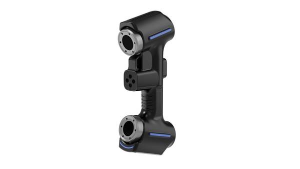
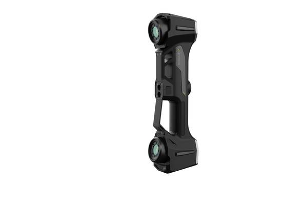
INSVISION industrial 3D scanners are built for these automotive inspection conditions. The industrial 3D scanner platform, for example, supports scanning areas up to 1100 mm × 800 mm with accuracy up to 0.020 mm, making it suitable for large stamping checks and precision powertrain work alike. A tracker depth of field of 2300 mm reduces repositioning on large assemblies.
Weight these five criteria to your facility’s actual use cases. A scanner that excels in the lab but fails on the floor is not a savings; it is a second problem.
Frequently Asked Questions
What is a 3D scanner for automotive inspection?
A 3D scanner for automotive inspection captures part geometry digitally for comparison against CAD models, GD&T callouts, and tolerance requirements. It supports first-article inspection, in-process checks, and root-cause analysis without the setup time of traditional CMM fixtures.
Can a 3D scanner handle reflective automotive parts?
Reflective surfaces are common in automotive manufacturing. The scanner’s optical design and software compensation determine how well it handles these surfaces without excessive coating. Always validate on your actual production material.
How fast is a 3D scanner for automotive parts?
Scan speed varies by scanning area, resolution, and part size. Rather than chase a single number, measure the full scan-to-report cycle against your production cadence and sampling plan.
Does an automotive 3D scanner replace a CMM?
It complements CMM work. Scanners capture full-field geometry quickly for broader coverage; CMMs remain useful for specific tactile measurements. Many facilities use both within the same quality workflow.
What accuracy do I need for automotive 3D scanning?
Match accuracy to the feature you inspect. Powertrain features often require tighter tolerances than large body panels. Validate the scanner’s accuracy on your tightest critical feature, not on a flat calibration artifact.
How INSVISION 3D Scans Align With Automotive Quality Workflow Needs
How do you verify stamped components, powertrain parts, or chassis geometry without letting inspection become the bottleneck? That is the question quality leads keep circling back to when evaluating automotive 3D scanner options.
INSVISION industrial 3D scanners fit into these workflows because they target the same evaluation criteria many automotive teams already use. Stamped component inspection, for example, requires fast capture of complex surface geometry to check against GD&T callouts. Powertrain validation often involves dense point clouds for bore alignment and flange flatness.
Chassis work leans on large-area scanning to support design optimization and fit-up checks. Aftermarket reverse engineering needs clean mesh data from worn or discontinued parts.
The operational value comes from reducing inspection queues, not from adding another disconnected tool. When one scan can replace multiple manual measurements, first-article inspection and batch consistency checks move faster. Digital records also support compliance traceability without extra documentation labor.
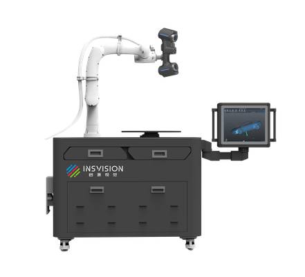
The key is fit for purpose. Confirm scan area, depth of field, and accuracy against your actual workpiece size and tolerance band before committing.
How to Run a Verifiable On-Site Trial to De-Risk Your 3D Scanner Purchase
Most teams overestimate how much they know about a scanner before it ever touches their production floor. They read the spec sheet, watch a demo on a clean sample part, and assume the workflow will hold up on a Tuesday afternoon with a dirty stamped crash beam and a delivery deadline looming. It usually does not. The gap is not dishonesty from vendors.
It is that every measurement task carries its own mix of surface finish, geometry, ambient light, operator skill, and CAD comparison logic. If you do not test against that mix, you are buying faith, not capability.
A verifiable on-site trial is the cheapest insurance you can buy before committing capital. It does not need to be complicated. Start by selecting two or three representative parts that cover your most common inspection challenges. A large stamped crash beam stresses scanning volume, stability, and time-to-mesh. A small precision transmission gear stresses edge sharpness, fine feature capture, and tolerance repeatability.
Pick parts that have caused real problems in the past, not parts that scan easily.
Then define success criteria before the vendor arrives. This is where most trials fall apart. If you do not write down what “good” looks like, you will talk yourself into whatever result you get. Tie each criterion to an operational goal. For a crash beam, measure the time to complete a full scan and produce a usable mesh.
For a transmission gear, check whether the scanner captures all critical tolerance features without excessive noise around edges. For both parts, confirm that the exported data drops into your existing CAD or inspection software without a separate conversion circus.
INSVISION supports these hands-on trials for automotive teams specifically so you can validate fit against your own parts and workflow before making a full investment.
Run the test side-by-side against your current inspection method. If you use a CMM today, time both processes on the same part. If you use manual gauges, compare the number of features captured and the repeatability across three runs. Do not expect the scanner to win every category. A CMM may still beat it on a single tight bore diameter.
The question is whether the scanner captures enough geometry fast enough to offset the CMM’s narrow focus. You are looking for the point where speed and coverage outweigh any loss in single-point precision.
Watch the operator, not just the output. A scanner that requires an expert to babysit every scan will not scale across shifts. Have your own technician run the trial, not the vendor’s application engineer. If your person cannot produce a usable result within half a day of training, that is a hidden labor cost you need to price in.
INSVISION’s automotive trials work best when your team drives the device, because that exposes software friction, alignment confusion, and any setup steps that sound easy in a demo but fall apart under time pressure.
Document everything in a simple pass/fail table. List each success criterion, the observed result, and a note on whether it matched expectations. Keep it internal. This is not a vendor scorecard. It is a decision record you can defend to your finance team and revisit six months after purchase when someone asks whether the investment paid off.
If the scanner fails a criterion, ask the vendor whether it is a hardware limit, a software setting, or a training gap. If the answer is vague, that is data too.
FAQs and Quick Validation Checklist for Automotive 3D Scanner Buyers
Most quality teams get burned at the validation stage, not the demo stage. They see a scanner work on a matte gray fixture block, then struggle when it hits a polished stamping die or an oily machined bracket on the line. Before you commit, work through these questions with your own parts in hand.
Can 3D scanners support IATF 16949 traceability requirements for automotive quality audits?
Yes, but only if the software workflow captures inspection results in a controlled, exportable format. IATF 16949 cares about documented evidence, revision control, and repeatability. A scanner alone does not make you audit-ready. You need a system that ties scan data to part number, cavity, date, operator, and measurement plan.
Ask whether the software can export first-article inspection reports, color maps, and deviation data to formats your quality department already archives. Some INSVISION workflows support automotive inspection tasks like stamping die verification and transmission housing checks, where traceability depends less on raw scan quality and more on how the data is stored and retrieved.
Confirm that the software locks measurement templates so different operators cannot alter GD&T callouts or tolerances between shifts. That is what auditors actually check.
How do 3D scanners handle reflective metal surfaces common in automotive stamping and machining?
Poorly, if you rely on default settings. Polished dies, machined aluminum housings, and bright stainless trim create specular reflection that can produce noisy data or dropouts. The practical fix is usually a thin developer spray or matting powder, but that adds a cleaning step and can affect fine feature measurement.
Some structured light scanners handle moderate reflectivity better than others through exposure control and multiple scan angles. For production environments where spraying every part is not acceptable, test the scanner on your shiniest, oiliest, most problematic surface before purchase. A scanner that struggles on a clean sample will fail on a production part with cutting fluid residue.
Do 3D scanning tools integrate with existing CMM and CAD software used in automotive quality departments?
Integration means different things to different teams. For some, it is exporting an STL or point cloud into PolyWorks or Geomagic for analysis. For others, it means feeding deviation data directly into a CMM reporting template or CAD comparison workflow. Most automotive quality departments already have established software for dimensional reporting. The scanner should fit into that workflow, not force a parallel system.
Ask whether the software exports native CAD comparison outputs, GD&T deviation reports, and CSV or QIF data for downstream SPC. If your team uses CMM results as the reference standard, run a correlation study between scanner output and CMM data on the same features. That correlation, not the scanner spec sheet, determines whether the tool gets accepted on the floor.
What level of staff training is needed to use 3D scanners on the production floor?
Less than CMM programming, but more than a go/no-go gauge. A quality technician can typically learn basic scan capture and alignment in a few days, but interpreting deviation maps and troubleshooting scan failures takes longer. The real training burden is not the hardware; it is understanding when a scan is valid and when it is misleading.
Operators need to recognize edge effects, poor alignment, and surface preparation issues. If you plan to put scanners in the hands of production operators rather than quality staff, budget for written work instructions, visual acceptance criteria, and periodic refresher training. A scanner that requires a dedicated expert for every measurement will not deliver the labor savings you are hoping for.
Quick Validation Checklist
- Define core use cases. List the three workpieces or inspection tasks that matter most. Stampings, castings, machined housings, weld fixtures, or reverse engineering. If a scanner cannot handle those three, it does not matter what else it does.
- Verify part and surface compatibility. Test on your actual materials: polished, machined, cast, oily, or coated. Do not accept vendor demo parts as proof.
- Test inspection speed against production cadence. Time the full workflow: setup, scanning, alignment, reporting. If it cannot keep up with your takt time or first-article turnaround, it becomes a bottleneck.
- Confirm workflow integration. Export a scan report into your existing quality software and CAD system. Check that tolerances, GD&T callouts, and part numbers carry through without manual rework.
- Run an on-site trial with your own parts. Use your operators, your environment, your reporting requirements. A scanner that works in a lab may fail next to a stamping press with vibration and ambient light.
Choose based on your operational constraints, not a vendor’s generic claims. A scanner that fits your workflow and your parts will pay back in reduced inspection time and fewer disputed measurements. One that does not fit will sit on a shelf.
Hangzhou Insvision Technology Co., Ltd.
Address: Building 1, No. 1399 Liangmu Road, Yuhang District, Hangzhou, Zhejiang 311121, China
Copyright © Hangzhou Insvision Technology Co., Ltd. All rights reserved.
Copyright © Hangzhou Insvision Technology Co., Ltd. All rights reserved.