

The Metrology Challenge: Selecting a 3D Scanner for Large-Object Inspection
For engineers and quality managers tasked with digitizing large-scale industrial assets, the process is far more complex than simply scaling up from bencht
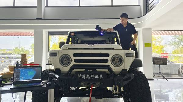
For engineers and quality managers tasked with digitizing large-scale industrial assets, the process is far more complex than simply scaling up from benchtop part scanning. The core challenge isn’t just size—it’s maintaining metrology-grade integrity across an extended coordinate system under real-world conditions.
This guide breaks down the critical technical and operational factors for selecting a 3D scanning solution capable of handling large objects, from wind turbine blades to vehicle frames.
The Core Hurdles in Large-Volume Metrology
When digitizing assets like aerospace fuselages or industrial molds, teams confront three persistent, interconnected problems that go beyond basic scanner specifications.
Scenario Snapshot
A practical way to read the article is through this scenario:
- The Core Hurdles in Large-Volume Metrology: When digitizing assets like aerospace fuselages or industrial molds, teams confront three persistent, interconnect…
- Critical Technical Capabilities for Reliable Results: Evaluating a scanner requires a focus on how it solves the above challenges.
- Matching the Scanner to Your Operational Profile: Your workflow dictates the optimal solution.
Critical Technical Capabilities for Reliable Results
Evaluating a scanner requires a focus on how it solves the above challenges. Key capabilities include:
- Volumetric Accuracy Specification: Look for a stated accuracy over the entire working volume (e.g., ±0.1mm over 10m), not just a single-shot measurement.
- Integrated Reference Systems: Solutions that use fixed or tracked reference points (like coded markers or laser trackers) maintain a stable global coordinate system, eliminating manual stitching and preventing drift.
- Spatial Tracking Technology: For continuous scanning of very large zones, optical or laser tracking systems follow the scanner’s position in real-time. This allows seamless, uninterrupted data capture across an aircraft hull or ship section without losing positional context.
- Robust Data Capture: The system must perform reliably in ambient light and resist data noise from vibration or reflective surfaces common in industrial settings.
Matching the Scanner to Your Operational Profile
Your workflow dictates the optimal solution. The choice hinges on two primary operational models:
- The Mobile Inspection Team
For teams moving between the factory floor, supplier sites, and field locations, portability and rapid setup are paramount. Key selection criteria include:
- Lightweight, ruggedized hardware.
- Automated coordinate system establishment via marker recognition.
- A large single-capture field of view to minimize repositioning.
- Ideal Applications: On-site MRO inspections, large casting verification, automotive chassis measurement, and mid-size aerospace component scanning.
- The Large-Volume Production Facility
For dedicated stations scanning entire vehicle frames or full aircraft sections, the priority shifts to maximizing throughput and seamless data continuity.
- Real-time spatial positioning systems are critical.
- The solution should enable extended, uninterrupted scanning zones.
- Integration with factory metrology networks and quality management systems (QMS) is essential.
The End-to-End Value of a Purpose-Built Workflow
Traditional methods for large-object inspection present a poor choice: subjective, non-digital manual measurements versus extremely expensive and inflexible fixed CMMs. Tape measures introduce human error and leave no digital record for traceability. Stationary large-volume CMMs require costly part fixturing and dedicated facility space, creating bottlenecks.
A dedicated large-object 3D scanning workflow collapses this compromise. It delivers a digital twin—a comprehensive point cloud—that enables:
- Full GD&T Analysis: Perform geometric dimensioning and tolerancing directly on the as-built asset.
- Direct CAD Comparison: Generate color deviation maps instantly to identify warpage, wear, or manufacturing defects.
- Digital Archiving: Create a permanent, auditable record for lifecycle management and quality compliance.
- Reverse Engineering: Accurately capture legacy parts or tooling for which digital models no longer exist.
The transition from theory to practice is evident in global manufacturing sectors:
- Automotive: A Tier-1 supplier uses large-object scanning to verify body-in-white fixtures against CAD models without stopping the production line, enabling rapid root-cause analysis of fitment issues.
- Aerospace: MRO teams employ portable, tracked systems to scan aircraft fuselage sections for damage assessment and airworthiness certification, dramatically reducing aircraft-on-ground (AOG) time.
- Energy: Wind turbine technicians capture full blade geometries in the field to analyze leading-edge erosion and structural integrity, informing repair decisions and lifespan projections.
- Heavy Machinery: Manufacturers of large-scale components use scanning for final assembly verification, ensuring that multi-ton structures meet precise alignment tolerances before shipment.
Selecting the Right Partner
For organizations like INSVISION, addressing these challenges means developing platforms that integrate high-volume scanning with intelligent reference systems. The goal is to provide tools that maintain coordinate integrity from the first scan to the last, delivering data that engineers can trust for critical decisions.
When evaluating solutions, focus on how the technology performs in scenarios that mirror your own—under time pressure, in demanding environments, and against the strict tolerances that define modern industrial quality.
Hangzhou Insvision Technology Co., Ltd.
Address: Building 1, No. 1399 Liangmu Road, Yuhang District, Hangzhou, Zhejiang 311121, China
Copyright © Hangzhou Insvision Technology Co., Ltd. All rights reserved.
Copyright © Hangzhou Insvision Technology Co., Ltd. All rights reserved.