

The Metrology Backbone: How 3D Scanning Reference Points Define Measurement Integrity
In precision manufacturing, the difference between a passed inspection and a costly rework order often hinges on an invisible framework: the network of 3D
In precision manufacturing, the difference between a passed inspection and a costly rework order often hinges on an invisible framework: the network of 3D scanning reference points. These fiducial markers are the bedrock of any scan, defining the coordinate system that aligns multiple data captures into a single, truthful digital twin. When this foundation is unreliable, so is every measurement derived from it.
Consider a common shop-floor scenario: an aerospace bracket requires a full first-article inspection. The initial scan session proceeds smoothly. However, a subsequent scan for a critical feature, performed hours or days later, uses reference points that have thermally drifted or were inadvertently disturbed.
The software forcibly aligns the two point clouds, but the resulting deviation report shows phantom errors on the part—artifacts of a misaligned coordinate system, not the physical component. The consequence isn’t just a confusing report; it’s delayed delivery, wasted engineering hours troubleshooting non-existent problems, and eroded confidence in the digital metrology process.
This accuracy gap stems from treating reference point placement as a casual setup task rather than a core metrology procedure. The principles are grounded in geometric dimensioning and tolerancing (GD&T). Reference points must create a stable, repeatable datum reference frame that mirrors the design intent on the drawing.
Establishing a Protocol-Driven Foundation
Effective reference point deployment is not arbitrary. It follows rules dictated by part geometry, size, and material.
Alignment Efficiency Through Integrated Technology
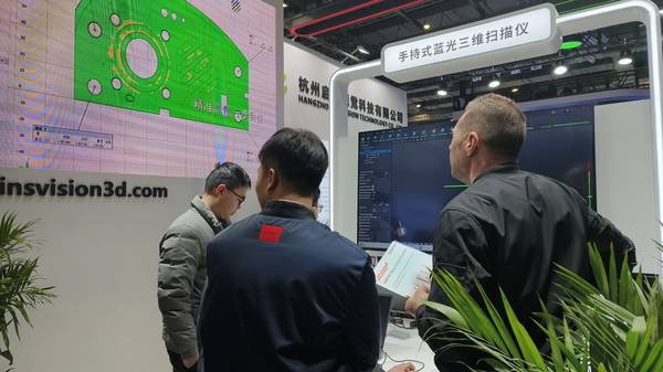
A significant operational bottleneck occurs when technicians spend more time manually aligning scans via reference points than capturing data. Modern handheld 3D scanners, like the INSVISION AlphaScan, address this by integrating advanced tracking technology. These systems use the reference points not just for post-processing alignment, but as active tracking targets during the scan itself.
This allows for real-time coordinate system stabilization, effectively “locking” the scanner’s position in space relative to the part. The workflow shifts from post-capture registration to continuous, validated measurement, reducing setup ambiguity and operator dependency.
The Operational Payoff of Standardization
The return on investing in a standardized reference point protocol is measured in consistency, not just speed. When every technician on the shop floor follows the same validated procedure—specific to part families—several key improvements manifest:
- Elimination of Interpretative Disputes: When alignment logic is standardized, debates over which scan dataset is “correct” disappear. The process becomes objective and repeatable, independent of the operator.
- Predictable Process Flow: Quality managers gain a reliable timeline for inspection tasks. There are fewer surprises, re-scans, or data validation crises holding up the production line.
- Seamless Data Fusion: Standardized reference points enable reliable comparison of data captured across different shifts, days, or even between in-house and supplier scan teams. This is critical for long-term trend analysis and supply chain quality management.
Ultimately, robust 3D scanning reference point protocols are a prerequisite for Industry 4.0 ambitions in quality control. They transform 3D scanning from a standalone inspection tool into a traceable, auditable, and deeply integrated metrology system.
For Western manufacturing teams operating under ASME, ISO, and lean principles, this foundation turns point cloud data into trustworthy, actionable intelligence for continuous improvement.
Hangzhou Insvision Technology Co., Ltd.
Address: Building 1, No. 1399 Liangmu Road, Yuhang District, Hangzhou, Zhejiang 311121, China
Copyright © Hangzhou Insvision Technology Co., Ltd. All rights reserved.
Copyright © Hangzhou Insvision Technology Co., Ltd. All rights reserved.