

How Do You Validate Laser 3D Scanner Results for High-Tolerance Industrial Parts?
laser 3d scanner: The High Stakes of Precision Part Inspection in Modern Manufacturing The High Stakes of Precision Part Inspection in Modern Manufacturing.
The High Stakes of Precision Part Inspection in Modern Manufacturing
Western manufacturing has shifted. Aerospace suppliers now juggle AS9102 first-article documentation alongside shrinking delivery windows. Medical device shops face FDA 21 CFR Part 820 traceability demands while automotive tier suppliers push IATF 16949 process control into every batch. The inspection room has become the bottleneck nobody budgets for.
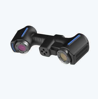
Selection Dimensions and Field Checks
| Focus Area | Decision Point | Deployment Note |
|---|---|---|
| The High Stakes of Precision Part Inspection in Modern… | Western manufacturing has shifted. | Aerospace suppliers now juggle AS9102 first-article documentation alongside shrinking delivery windows. |
| 6 Key Constraints That Define Laser 3D Scanner Fit for… | Most shops don’t fail because they bought a bad laser 3D scanner. | They fail because they bought the wrong one for the geometry, material, and inspection workflow sitting right in front of them. |
| 1) Part Geometry | Start with the surfaces you actually need to capture. | Deep holes, internal channels, undercuts, and narrow slots are where many scanners fall apart. |
| 2) Material Properties | Material drives scan noise more than most buyers expect. | Reflective aluminum and polished stainless can create specular reflections that either blind the sensor or generate false surface data. |
Traditional contact CMM workflows were built for a different era. A first-article inspection might tie up a machine for hours. In-process checks pull parts off the line and queue behind other jobs. Incoming verification of supplier parts creates another backlog. Each step depends on specialized CMM programmers and operators, so throughput caps with headcount.
When a high-mix, low-volume job arrives, the measurement routine itself becomes the lead time problem.
This section examines how a laser 3D scanner deployment changes that equation. We will look at what makes these inspection tasks genuinely difficult, then walk through capture, alignment, rescan, and validation steps that determine whether a scanner actually fits your quality workflow. The goal is not to replace every CMM, but to relieve the constraints that conflict with lean manufacturing and Industry 4.0 delivery cadence.
For solution engineers evaluating INSVISION industrial 3D scanner options, the priority is verifying performance against your specific part geometry, tolerance stack, and documentation requirements before committing floor space and training budget.
6 Key Constraints That Define Laser 3D Scanner Fit for Your Operation
Most shops don’t fail because they bought a bad laser 3D scanner. They fail because they bought the wrong one for the geometry, material, and inspection workflow sitting right in front of them. A scanner that nails a stamped bracket may choke on a turbine blade’s fir-tree root. One that handles matte castings beautifully can produce useless data on polished aluminum. Fit is not about resolution on a spec sheet.
It’s about whether the capture strategy, alignment approach, rescan logic, and validation routine can hold up under your actual tolerances, your floor conditions, and your takt time. Before evaluating any hardware, run each job through six constraints. They define whether a laser 3D scanner becomes a daily inspection tool or an expensive shelf ornament.
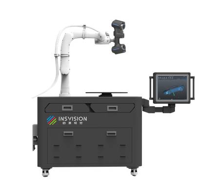
1) Part Geometry
Start with the surfaces you actually need to capture. Deep holes, internal channels, undercuts, and narrow slots are where many scanners fall apart. A single laser line can reach into a cooling hole or an internal thread root where a multi-line pattern simply cannot reconstruct clean data. Free-form surfaces common in aerospace turbine components and medical implants demand high point density without excessive noise.
Micro-features like small radii, edge breaks, and engraved serial numbers require enough resolution to resolve the feature, not just approximate it. Ask the vendor how the scanner behaves at the bottom of a pocket or across a sharp edge transition. If the answer is vague, test it. Bring a real part with the worst geometry you inspect, not a flat demo block.
2) Material Properties
Material drives scan noise more than most buyers expect. Reflective aluminum and polished stainless can create specular reflections that either blind the sensor or generate false surface data. Carbon fiber composites often scan well, but the weave pattern can introduce texture noise that complicates CAD comparison.
Translucent medical polymers scatter light unpredictably, producing artifacts that look like real surface deviation but aren’t. The right laser 3D scanner for these jobs typically uses blue laser lines with controlled exposure settings and the ability to adjust scan parameters per surface.
If your part mix includes shiny and dark and translucent materials in the same assembly, you need a scanner that can switch strategies without a full recalibration. INSVISION’s industrial scanner line addresses this through configurable scanning modes, including single-line capture for difficult surfaces, rather than forcing one fixed pattern onto every material.
3) Tolerance Requirements
This is where GD&T callouts separate inspection-grade tools from reverse-engineering toys. If you’re checking true position at 0.050 mm, most mid-range scanners will work. If you’re holding profile tolerances under 0.025 mm on a sealing surface or a bearing bore, you need a system with verified volumetric accuracy, not just high resolution. Micron-level requirements on safety-critical components demand more than a good scan.
You need a stable alignment strategy, repeatable fixture or reference targeting, and a validation routine that proves the scanner measures a known artifact within tolerance before every shift. Don’t accept a vendor’s accuracy claim without asking how it was tested, under what temperature conditions, and over what scan volume. For larger parts, tracker-assisted scanning changes the accuracy conversation entirely.
A scanner with a wide depth of field and a separate tracking volume can hold accuracy across a large weldment or airframe structure where a fixed-volume desktop scanner cannot.
4) Operating Environment
Shop floor conditions kill good scan data. Vibration from stamping presses or CNC spindles can blur point clouds if the scanner lacks sufficient frame rate or stabilization. Fluctuating ambient temperature shifts both the scanner and the part, especially on large aluminum components. Ambient light from overhead halogens or sunlight through a bay door can wash out laser lines.
If your inspection has to happen next to the machine tool rather than in a clean lab, the scanner must be built for that reality. Ask about operating temperature range, vibration tolerance, and how the system handles changing light. A scanner that requires a dark, climate-controlled room may be fine for a metrology lab but useless for in-process checks.
INSVISION’s laser 3D scanner designs account for these variables through industrial-grade sensor housings and scanning modes that maintain data quality in less-than-ideal lighting.
5) Takt Time Alignment
Scan speed only matters in relation to your production cadence. A scanner that takes four minutes to capture a part is irrelevant if the line produces one part every ninety seconds and you’re committed to 100% inspection. Conversely, if you’re doing first-article inspection or periodic spot checks, speed matters less than data completeness. Define the inspection interval first.
For 100% inline inspection, scan and analysis time must fit inside the takt window with margin for part loading and unload. For batch or spot-check workflows, a slower but more thorough scan may be acceptable.
The operational question is not “how fast is the scanner” but “how many parts can a single operator scan, analyze, and disposition per shift without creating a bottleneck.” That number depends on scan mode selection, automation potential, and how much manual alignment the software demands.
6) Data Deliverables
The scan is only the beginning. What you deliver to engineering, quality, and the customer defines whether the tool has business value. GD&T reports with color maps and pass/fail callouts are the baseline for most dimensional inspection. CAD comparison files let design teams see exactly where the manufactured part deviates from nominal.
Traceable quality records matter when you’re shipping into aerospace, medical, or automotive supply chains with audit requirements. The scanner must export data in formats your downstream systems can consume, whether that’s a native CAD file, a mesh, or a structured report. If the software cannot produce an inspection report without a separate seat of expensive third-party software, factor that into the total cost.
INSVISION’s workflow supports these deliverables through software designed to move from scan to report without exporting raw point clouds into a disconnected analysis tool.
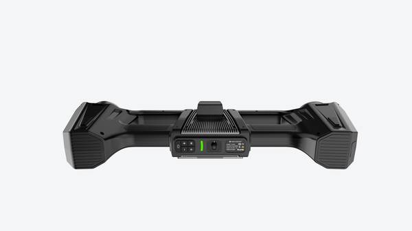
Fit is not a single specification. It’s the intersection of these six constraints with the parts you actually make, the tolerances you actually hold, and the production rhythm you actually run. A laser 3D scanner that fits your operation will reduce inspection bottlenecks, cut rework from late-discovered deviations, and give quality engineers data they can defend in a customer audit.
The wrong one will generate noise, slow the line, and erode trust in digital inspection. Test against real parts, real materials, and real floor conditions before you commit. That diagnostic discipline is what separates a smart capital purchase from an expensive experiment.
Common Capture Risks That Undermine Laser 3D Scan Data Reliability
Most shops treat a laser 3D scanner as a measurement tool. That assumption causes more trouble than any hardware limitation. In practice, the scanner is only one part of a capture system. The fixture, reference targets, operator technique, surface condition, and validation protocol all influence whether the final mesh actually represents the part.
A solution engineer walking into a typical first-article inspection or reverse engineering job sees the same failure points repeat across automotive, aerospace, and energy shops.
Misalignment is the most common one. Teams place reference points inconsistently, or they rely on a part fixture that shifts slightly during scanning. The scanner tracks fine. The data drifts. By the time anyone notices, the point cloud has a subtle twist that violates GD&T callouts downstream. Deep boreholes, undercuts, and internal channels create a second problem: data gaps.
A laser 3D scanner cannot capture what it cannot see. If the workflow does not include a planned rescan strategy for occluded geometry, the operator either accepts missing data or spends hours patching holes manually.
Surface reflection adds another layer of difficulty. Shiny machined surfaces, carbon fiber, and certain coatings scatter the laser line unpredictably. The result is noise, false edges, or localized data loss. Resolution drop-off across large parts compounds this. A scan area optimized for a small bracket may not hold the same point density across a meter-long casting. Then comes operator variability.
Different shifts, different hands, slightly different scan paths. The same part scanned twice produces two datasets that do not overlay cleanly. That is a repeatability problem, not a scanner problem, but it still lands on the quality record.
These risks do not stay in the lab. They convert directly into rework hours, delayed inspection cycles, and quality documentation that fails customer audit. A non-compliant scan report erodes trust faster than a late shipment. The operational cost hides in the time spent rescanning, re-aligning, and explaining why the data does not match the CAD model. Structured validation is not optional.
It is the only way to make a laser 3D scanner produce data that engineering, quality, and procurement can all rely on.
How INSVISION Laser 3D Scanning Solutions Align With Industrial Inspection Constraints
On a typical shop floor, inspection bottlenecks rarely come from a single bad measurement. They come from the sequence of events around it. A first-article check stalls while someone builds a fixture. A complex casting with deep pockets and angled bores takes three setups on a CMM. A rework decision waits on a report that only one senior inspector knows how to interpret.
None of these problems show up as a line item on a capital equipment request, but they all show up in overtime hours, missed delivery windows, and quality disputes that erode margin.
The constraint framework for industrial inspection is therefore not about scanner resolution in isolation. It is about whether the measurement tool fits the geometry, the environment, and the tolerance band without adding labor or safety overhead. INSVISION laser 3D scanner solutions are structured around that fit.
The goal is not to replace every CMM on the floor, but to remove the specific inspection tasks that consume disproportionate time relative to their value.
For complex geometry tasks, deep holes and fine internal features are the usual failure points. A scanner that captures surface data quickly on open faces may still leave voids where a single laser line cannot reach. INSVISION systems address this with specialized scanning modes.
The single blue laser line mode, for example, is intended for deep hole scanning, giving the operator a way to pull usable data out of recessed areas that would otherwise require destructive sectioning or a custom probe setup. The seven blue laser line mode handles precision scanning across broader surfaces. The point is that the operator selects the mode based on the feature, not based on a default setting.
That reduces the number of scans that look complete in preview but fail during mesh processing.

On a high-traffic shop floor, eye safety and integration constraints matter as much as scan speed. If a laser scanner requires barriers, controlled access, and a dedicated operator station, it becomes another isolated inspection cell rather than a tool that can move with the work. INSVISION offers eye-safe laser options that support deployment directly in production workflows.
This matters for Western manufacturers running lean operations where inspection is embedded in the line, not pushed to a separate lab. When a scanner can sit next to a machining center or a weld cell without requiring safety interlocks and signage, it changes how often the team actually uses it. The tool becomes part of the process, not a gated resource.
For high-tolerance applications, the concern shifts to repeatability and standards compliance. A scanner that produces a good-looking point cloud is not enough when the part must meet ISO or ASME quality requirements. INSVISION scanners deliver consistent precision performance, which is the operational phrase that matters.
Consistency across shifts, across operators, and across repeated measurements is what allows a quality manager to trust the data enough to use it for first-article documentation or in-process trending. When the measurement system is stable, the inspection result becomes a defensible record rather than a subjective judgment call.
The operational value of this approach shows up in three areas. First, rework drops because problems are caught earlier and with better positional context. Instead of discovering a form error after machining, the team sees the deviation while the part is still in process. Second, inspection cycles shorten because the scanner captures full surface data in one or two passes rather than requiring multiple CMM setups.
Third, quality traceability improves because the digital scan becomes part of the job record. For Western buyers in automotive, aerospace, medical device, and energy sectors, that traceability supports both internal continuous improvement and external customer audits.
INSVISION does not present a single scanner configuration as the answer for every operation. The matching process starts with the scan object, the inspection task, the site constraints, and the required data deliverable. From there, the appropriate scanning mode and system configuration follow. That is a deliberate departure from specification-led selling.
A resolution number on a datasheet does not tell a production manager whether the scanner will work next to a robot cell or whether an operator can capture a deep bore without a mirror attachment. The use case does.
The result is a measurement resource that reduces the hidden costs of inspection: fewer rework loops, less dependence on specialized measurement personnel, faster release of conforming parts, and a digital record that holds up under audit. Those are the outcomes that show up in operating margin, not just in the quality department.
Validation Checklist and Deployment Boundaries for Laser 3D Scanners
Most teams assume a laser 3D scanner either works in their plant or it doesn’t. That’s the wrong question. The right one is whether the system holds up under your specific inspection task, operator variation, and shop floor conditions.
Start with constraint mapping. Confirm the scanner’s scanning area and depth of field match your largest and smallest features. For example, INSVISION’s industrial 3D scanner offers a scanning area up to 1100 mm × 800 mm and a 650 mm scanner depth of field. If your parts exceed that envelope, you’ll need tracker-assisted coverage or staged scans.
Next, run a gage R&R on calibrated reference parts. Have at least two operators scan the same features across three shifts. Watch for repeatability drift, not just average deviation. Then test under real conditions: vibration from nearby presses, temperature swings near bay doors, and dust. A scanner that passes in a metrology lab can fail 20 feet from a machining cell.
Validate data deliverables against ISO 10360 for acceptance testing and ASME Y14.5 for GD&T callouts. Finally, lock a calibration interval before procurement, not after. Unplanned drift erodes trust faster than any spec sheet. Deployment succeeds when diagnostic evidence, not vendor claims, drives the sign-off.
Hangzhou Insvision Technology Co., Ltd.
Address: Building 1, No. 1399 Liangmu Road, Yuhang District, Hangzhou, Zhejiang 311121, China
Copyright © Hangzhou Insvision Technology Co., Ltd. All rights reserved.
Copyright © Hangzhou Insvision Technology Co., Ltd. All rights reserved.