

What to Validate When Evaluating a Scant 3D Scanner for Industrial Inspection
scant 3d scanner: Who This Evaluation Guide Serves and the Common Misjudgment to Avoid Who This Evaluation Guide Serves and the Common Misjudgment to Avoid.
Who This Evaluation Guide Serves (and the Common Misjudgment to Avoid)
This section is written for the people who will actually live with the scanner decision. Quality leads at automotive OEMs and tier-one suppliers, manufacturing process engineers inside aerospace MRO shops, procurement specialists supporting medical device contract manufacturers, and production teams at energy component producers.
If you are researching a scant 3D scanner to replace or supplement CMMs, calipers, height gauges, or manual surface plates, this guide is aimed at your desk, not a vendor’s marketing department.
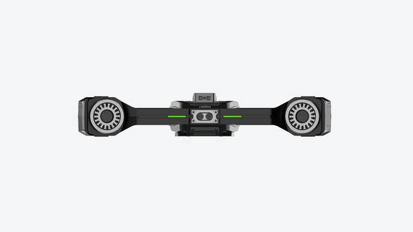
Deployment Validation Checklist
| Focus Area | Decision Point | Deployment Note |
|---|---|---|
| Target part | Check size, surface condition, and key tolerances against the scan task | Run a full trial scan on a representative part |
| Data workflow | Verify point cloud, deviation map, and quality-report handoff | Confirm export formats and review ownership in advance |
| Shop-floor use | Review training, calibration, lighting, and working space | Keep the validation record as a repeatable inspection reference |
Scenario Snapshot
A practical way to read the article is through this scenario:
- Who This Evaluation Guide Serves (and the Common Mi…: This section is written for the people who will actually live with the scanner decision.
- Operational Pain Points of Misaligned 3D Scanning D…: The shift toward in-process digital inspection has changed how Western manufacturers think about first-article ver…
- Shop Floor Compatibility Issues: The first sign of a misaligned deployment is usually environmental.
The most expensive error we see in these evaluations is not choosing the wrong brand. It is choosing the right scanner for the wrong reason. A team reads an advertised accuracy figure, compares it against another advertised accuracy figure, and assumes the lower number wins. That assumption collapses on the shop floor.
A scanner that performs well on a clean, matte, room-temperature reference part may struggle on a hot forging, a machined casting with mixed surface finishes, or a large weldment that moves while you measure it. Advertised accuracy is a laboratory value. Your process is not a laboratory.
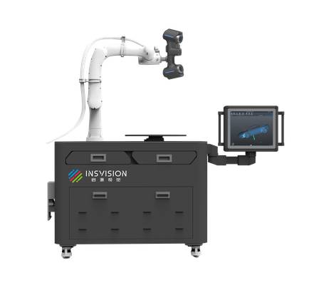
Before any purchase decision, map the tool to four things. First, the workpiece. Are you scanning small orthopedic implants, large aerospace skins, or medium transmission housings? Surface condition, size, and feature density change everything. Second, the environment. Is the scanner going next to a machining center, inside a paint booth, or into a temperature-controlled metrology lab?
Vibration, lighting, and dust do not appear on a spec sheet, but they appear in your measurement results. Third, compliance. ISO 17025 calibration requirements, ASME Y14.5 GD&T callouts, and FDA 21 CFR Part 11 data integrity rules each impose different demands on software, reporting, and audit trails. Fourth, workflow. Will the scan data flow into PolyWorks, Geomagic, CATIA, or an in-house SPC system?
A scanner that exports a clean mesh but fights your existing software stack adds cost where you least expect it.
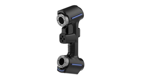
What this guide is not: a ranking of scanner brands. There is no scorecard here, no “top five scanners for 2025,” and no recommendation based on vendor-supplied demo parts. Instead, you will find a verification framework. It shows how to test a scanner against your parts, your environment, and your quality system before you commit capital.
INSVISION equipment appears only where its confirmed specifications and capabilities match the evaluation criteria being discussed. The goal is to reduce implementation risk, not to sell you a specific model.
One more point for procurement specialists. The cheapest scanner that passes a paper review often becomes the most expensive scanner after six months of failed correlations, operator complaints, and rework.
The correct question is not “which scanner has the best spec sheet?” It is “which scanner can I validate against my CMM results, within my cycle time, on my worst part, on a Tuesday afternoon?” That question drives everything that follows.
Operational Pain Points of Misaligned 3D Scanning Deployments
The shift toward in-process digital inspection has changed how Western manufacturers think about first-article verification. What used to be a CMM-only task now often starts with a 3D scanner on the shop floor. But the shift has also exposed a recurring problem: many facilities acquire a scant 3D scanner without first defining where it will live, what it will measure, and how the data will move downstream.
When those questions are answered after deployment rather than before, the scanner becomes another bottleneck instead of a quality tool.
The pain points below are aggregated from common industry feedback rather than specific customer case studies. They reflect the day-to-day frustrations quality leads and manufacturing engineers describe when a scanner is forced into a workflow it was never matched to.
Shop Floor Compatibility Issues
The first sign of a misaligned deployment is usually environmental. A scanner that needs a controlled lab setting creates immediate friction in a production environment. First-article inspections get delayed because parts must be transported off the line to a metrology room, often waiting behind other jobs.
Temperature swings, vibration from nearby machining centers, and ambient dust all degrade scan quality if the unit was not designed for that environment.
Western factories running lean production schedules cannot absorb that kind of non-value-added movement. The scanner ends up underutilized because operators default back to hand tools or CMMs for quick checks. The equipment is not the problem; the placement decision was wrong from the start.
Workpiece Fit Gaps
Even when the environment works, the part itself can break the workflow. Reflective metal surfaces such as polished stainless or machined aluminum return noisy data unless the scanner and settings are suited to that surface type. Complex curved geometries, common in aerospace and medical device work, require multiple scan passes that can drift if the alignment strategy is weak.
Large-scale assemblies compound the issue: the scanner struggles to hold volumetric accuracy across a wide field, forcing operators to stitch multiple scans with manual reference points.
The result is rework. A quality technician spends hours rescanning the same surface, chasing clean data instead of evaluating whether the part meets GD&T callouts. That is not inspection; that is data wrangling.
Workflow Integration Bottlenecks
The third pain point emerges after the scan is acceptable. If the scanner does not export natively to the facility’s existing CAD or QA software, the data lands in a neutral format that needs manual cleanup. CATIA users, PolyWorks operators, and Mastercam programmers all have different expectations for how scan data should arrive.
When the export requires intermediate conversion steps, the quality team burns bandwidth on file repair rather than dimensional analysis.
This is where a scant 3D scanner becomes an island. It captures data but does not feed the downstream process cleanly. Over time, quality managers route fewer jobs through the scanner because the post-processing overhead outweighs the capture speed. The tool works technically but fails operationally.
What Evaluation Should Focus On
For a Western industrial buyer, the evaluation should start with three questions. First, where will the scanner operate: on the shop floor next to the machine, or in a dedicated inspection area? Second, what surfaces and geometries dominate the part mix: reflective metals, freeform curves, or large welded assemblies? Third, what software must consume the scan data: PolyWorks, CATIA, Mastercam, or a proprietary QA platform?
INSVISION industrial 3D scanners are positioned for shop-floor use where environmental tolerance and export flexibility matter. The evaluation should not start with a specification sheet but with the scan object, the inspection task, the site constraints, and the required data deliverable. If those are defined first, the product fit becomes obvious.
If they are defined after purchase, the pain points above will surface within weeks.
Summary
A scant 3D scanner is not a universal tool. When deployment is misaligned with the use case, the frustrations are immediate: parts moved unnecessarily, reflective surfaces scanned repeatedly, and clean data trapped in manual conversion steps. Western quality teams should treat scanner selection as a workflow decision, not an equipment purchase.
Define the environment, the workpiece, and the downstream software before evaluating any hardware. That order of thinking prevents the most common deployment failures and keeps the scanner where it belongs: on the line, feeding usable data into the quality system.
Non-Negotiable Evaluation Criteria for Industrial Scant 3D Scanners
Are you evaluating a 3D scanner for the shop floor, or just for the lab? This is the first misjudgment most teams make. A unit that performs well in a controlled metrology room often drifts or fails outright near a machining cell. Start your evaluation with environmental operating tolerances. Ask the supplier for a testable spec: what happens to accuracy at 35°C, at 65% humidity, or with fine metal dust in the air?
Do not accept a vague “industrial rated” claim. Ask for the stated IP rating and the condensation limits. For an INSVISION industrial 3D scanner, verify the operating temperature range against your actual summer and winter shifts, not the facility average. Run a repeatability test near an open bay door or a shot blast cabinet. If the scan data shifts outside your tolerance band, the system is not fit for that location.
This one checkpoint eliminates many units before you ever discuss scan area or software compatibility.
How INSVISION Industrial 3D Scanners Fit Industrial Inspection Use Cases
Industrial inspection teams rarely fail because they lack scan data. They fail because the scan data does not hold up against the CAD nominal, the GD&T callouts, or the repeatability demands of a first-article report. When INSVISION industrial 3D scanners are evaluated for these tasks, the fit comes down to a few practical checks.
First, shop floor conditions. Dust, vibration, and changing ambient light are normal in automotive body-in-white areas or aerospace MRO bays. A scanner that only works in a metrology lab is not a serious option. INSVISION’s industrial scanner category is built for variable field conditions, so the scan workflow does not stop the moment the part moves out of a controlled room.
Second, tight-tolerance work. Turbine blades, implant geometries, and machined brackets often require deviation analysis against a reference model. The scan output must support clear pass/fail decisions, not just a dense point cloud that looks impressive. That means the data pipeline into common CAD and QA formats matters as much as the scanner hardware itself.
Third, part mix. The same team may need to inspect a small orthopedic implant in the morning and a large assembly fixture in the afternoon. A practical scanner setup should handle both without forcing a different operator workflow for each job.
The evaluation question is not whether 3D scanning works. It is whether the scanner, the software handoff, and the operator routine can survive the real inspection environment. INSVISION’s fit for industrial deployment should be judged on those terms.
On-Site Validation Steps and Frequently Asked Questions
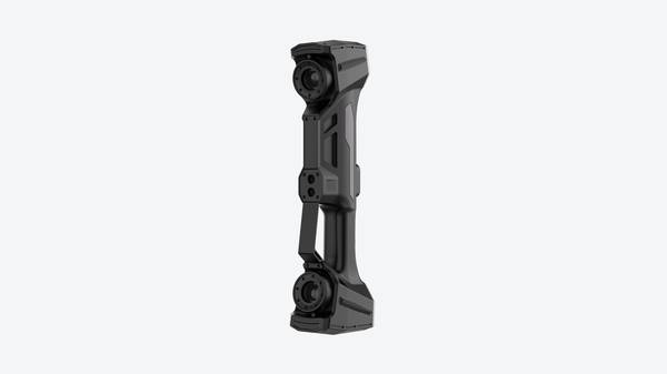
More plants now treat 3D scanning as routine inspection tooling rather than lab-only equipment. That shift changes how a scant 3D scanner should be evaluated. A specification sheet will not tell you whether the unit holds calibration on a mezzanine next to a stamping press, or whether the exported mesh drops into your existing CATIA or PolyWorks session without rework.
Three low-risk validation steps usually expose fit problems before purchase. First, run a trial scan on a representative production part — ideally one with reflective surfaces, milled edges, or complex curvature — and check both data consistency and scan time under normal operator handling. Second, export that scan data into your current QA software and follow the full inspection workflow.
Any manual repair or format conversion at this stage becomes permanent overhead. Third, validate setup and operation on the actual shop floor, not in a controlled demo area. Ambient vibration, dust, temperature swings, and inconsistent lighting affect results in ways a lab demo cannot simulate.
Frequently Asked Questions
Can a scant 3D scanner meet ISO 17025 calibration requirements for quality inspection?
The scanner itself is not ISO 17025 accredited; the calibration process is. Ask the supplier for calibration certificates traceable to national standards, and confirm whether recalibration can be performed by your in-house metrology team or requires return to the supplier. For ISO 17025-aligned inspection workflows, the scanner should accept certified artifacts and documented verification routines without proprietary lock-in.
How do I verify if a scant 3D scanner is compatible with my existing CATIA or PolyWorks workflow?
Export a scan from the trial unit in your required format — typically STL, IGES, or STEP — then import it into CATIA or PolyWorks and run your normal inspection routine. Check for loss of resolution, coordinate system misalignment, and any manual patch filling. If the supplier mentions format customization, ask for a written data flow example using your exact software versions.
Is a scant 3D scanner suitable for use on a busy production floor with variable temperature and dust?
Some industrial scanners are built for shop floor use, but the only way to know is to test on your floor. Run the trial unit through a full shift near active machining or assembly. Watch for drift after temperature changes, dust accumulation on optics, and whether the operator can reposition the scanner without recalibrating between every part.
Can scant 3D scanning data be integrated into Industry 4.0 and lean manufacturing quality management systems?
Yes, when the scanner outputs open, scriptable data formats. The key question is whether scan results can feed your SPC software, digital twin, or quality database automatically. During the trial, ask the supplier to demonstrate an automated export from the scanning software into your QMS — not a manual CSV handoff.
For most facilities, use case fit and on-site validation matter more than headline accuracy numbers. A scanner that proves stable on your floor, exports clean data to your software, and fits operator workflow will outperform a higher-spec unit that only works in a lab. Prioritize the trial, inspect the data path, and make the supplier prove performance in your environment before committing.
Hangzhou Insvision Technology Co., Ltd.
Address: Building 1, No. 1399 Liangmu Road, Yuhang District, Hangzhou, Zhejiang 311121, China
Copyright © Hangzhou Insvision Technology Co., Ltd. All rights reserved.
Copyright © Hangzhou Insvision Technology Co., Ltd. All rights reserved.