
Integrating a 3D Measurement Tool into High-Tempo Production
In this articleShop Floor Reality: Handheld Scanning at the WorkstationAlphaScan Engineering: Accuracy at 7.1 Million Points Per SecondGlobal Validation: C...
For Western manufacturers, this means deploying a system that validates safety-critical components without becoming the constraint in a lean process.
Shop Floor Reality: Handheld Scanning at the Workstation
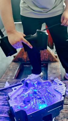
The practical difference is visible immediately. Instead of scheduling time on a fixed CMM and transporting heavy components, operators can deploy a handheld scanner directly at the workstation. INSVISION’s systems, like the AlphaScan, capture up to 7.1 million measurements per second, turning any stable surface into a temporary scanning site.
Common Questions
What should teams check when evaluating Shop Floor Reality: Handheld Scanning at the Workstation?
The practical difference is visible immediately.
What should teams check when evaluating AlphaScan Engineering: Accuracy at 7.1 Million Points Per Second?
A common assumption is that high scanning throughput compromises accuracy.
What should teams check when evaluating Global Validation: Certifications for Western Markets?
Precision in a climate-controlled lab is one thing;
This process generates a comprehensive point cloud, visualized as a color-coded deviation map overlaid on the CAD model. For a team verifying a large stamping die or an intricate turbine blade, this means seeing GD&T compliance across the entire surface, not interpolating it from a few dozen contact points.
Validation that once took hours is resolved in minutes, with the scan data aligned to reference standards within PTB-certified software. This bridges the gap between digital design and physical part, ensuring each production run meets spec without disrupting the flow.
AlphaScan Engineering: Accuracy at 7.1 Million Points Per Second
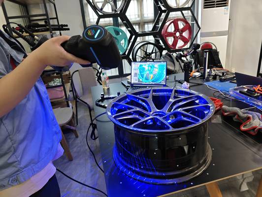
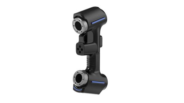
A common assumption is that high scanning throughput compromises accuracy. The development of the INSVISION AlphaScan challenged this by achieving a single-point accuracy of 0.015–0.02 mm while scanning at 7.1 million points per second. The solution hinged on an optical system using 50 intersecting blue laser lines.
This configuration captures deep cavities and reflective surfaces—common on cast or polished parts—that often cause data drop-out in simpler, single-line systems. Furthermore, the system’s marker-free tracking and real-time calibration allow an operator to maintain a steady scan path in confined spaces or across large assemblies, eliminating the setup time required for fixed photogrammetry targets.
This 3D measurement tool is optimized for comprehensive surface inspection and volumetric coverage of large parts, not for isolated, ultra-high-magnification feature checks.
Global Validation: Certifications for Western Markets
Precision in a climate-controlled lab is one thing; reliable performance on a vibrating factory floor in Stuttgart or Seattle is another. INSVISION’s transition to a global provider was cemented by securing CE, FCC, and CNAS certifications—non-negotiable credentials for entering Western automotive, aerospace, and medical manufacturing ecosystems.
Deployed in over 20 countries, these systems are used at automotive OEM quality gates for rapid first-article inspection and in aerospace MRO facilities for certified component verification. This global footprint demonstrates that the hardware is built for robustness, and the software outputs are trusted for traceable reporting.
When evaluating any metrology system, confirm its calibration certificates are recognized by your industry’s quality auditors.
Software Workflow: From Point Cloud to GD&T Compliance
The scanner hardware captures data, but the software delivers the decision. INSVISION PTB-certified software suite is designed to close the loop between scanning and engineering validation. It automatically aligns multi-source data—for instance, combining scan data from multiple part orientations—and instantly generates an intuitive color deviation map.
Built-in GD&T tools allow engineers to apply tolerance callouts directly onto the 3D model, checking them against ASME Y14.5 or ISO GPS standards. The final output is a standardized inspection report dashboard, generated in one click. This workflow is particularly effective for intricate part geometries, such as those from additive manufacturing, where automated deviation analysis replaces volumes of manual measurement.
Before beginning batch analysis, always verify the alignment procedure for your physical reference standards to ensure on-site accuracy.
AI-Guided Inspection: Reducing Operator Dependency
The evolution is from passive scanning to active guidance. By leveraging high-speed capture, INSVISION systems now integrate automated pattern recognition. This AI-guided function assists operators by highlighting unscanned areas or potential anomalies in real-time, ensuring complete coverage of complex geometries like a full vehicle body panel or a sculptured mold.
This turns the 3D measurement tool into an active participant in the quality loop, reducing operator dependency and improving repeatability across shifts. This capability was refined through iterative feedback from sectors like aerospace, where consistent, documented processes are paramount.
Selection Criteria: Matching the Tool to Your Production Context
When assessing if this approach fits your operation, focus on the part characteristics. Verify that your target tolerance bands align with the system’s validated range, and review the specific regulatory requirements for your region. This 3D measurement tool performs best on large castings, stamped panels, and complex additive manufacturing geometries where full-surface coverage delivers more value than spot checks.
For isolated feature inspection with micron-level tolerances on small precision parts, alternative metrology approaches may be more appropriate. To determine technical compatibility, share your typical part material, maximum dimensions, surface finish, and production line takt time with the INSVISION engineering team. Their assessment will be based on your actual validation scenario, not theoretical specifications.
Hangzhou Insvision Technology Co.,Ltd.
Address: Building 1, No. 1399 Liangmu Road, Yuhang District, Hangzhou, Zhejiang 311121, China