
Overcoming On-Site 3D Scanning Bottlenecks
In this articleWhy Legacy Scanning Workflows Stumble on the Shop FloorDeploying Metrology-Grade Scanning Where It's Needed MostFrom Raw Scan to Auditable D...
For teams verifying complex geometries in situ, a streamlined scanning workflow is no longer a luxury but a necessity for maintaining lean production flow and closed-loop quality.
Why Legacy Scanning Workflows Stumble on the Shop Floor
The bottleneck often lies not in sensor accuracy but in workflow integration. Fixed metrology stations create significant part-handling overhead, forcing operators to move heavy or thermally sensitive components instead of measuring them at the point of assembly. Even line-side systems can suffer from calibration drift due to variable lighting or thermal shifts in active production zones, compromising repeatability.
Term Notes
The bottleneck often lies not in sensor accuracy but in workflow integration.
Deploying Metrology-Grade Scanning Where It’s Needed Mo…Verifying a complex casting or a confined weld bead no longer requires hauling the part to a lab.
From Raw Scan to Auditable Decision: Streamlining the D…The true value of 3D scanning is realized in post-processing.
Validating System Fit for Your Production EnvironmentA datasheet’s metrology-grade specifications do not guarantee on-site performance;
The friction extends to software, where disconnected scanning-to-inspection pipelines require manual point cloud alignment and report drafting—a tedious process exacerbated by challenging geometries like deep undercuts or surfaces with mixed reflectivity. INSVISION approaches this by unifying high-precision data acquisition with intelligent processing, ensuring shop-floor conditions do not dictate the pace of verification.
Deploying Metrology-Grade Scanning Where It’s Needed Most
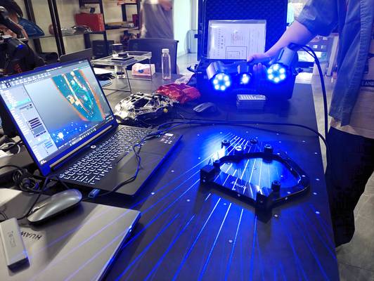
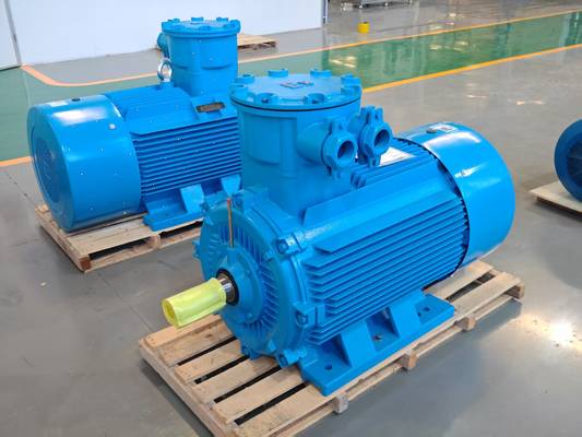
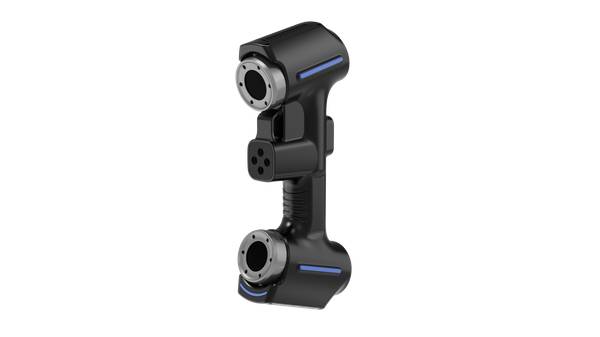
Verifying a complex casting or a confined weld bead no longer requires hauling the part to a lab. The INSVISION AlphaScan handheld 3D scanner brings the measurement capability directly to the component. Its portability allows operators to reach confined spaces and intricate features on everything from small precision components to large vessel sections, effectively eliminating the need for dedicated fixture rooms.
The system’s AI-driven scanning engine captures data rapidly across varying surface conditions, while high-speed USB data transfer maintains stability during continuous operation on large assemblies. For teams that need to capture high-precision data in difficult-to-reach locations, this approach provides the necessary flexibility without sacrificing metrology-grade results.
From Raw Scan to Auditable Decision: Streamlining the Digital Thread
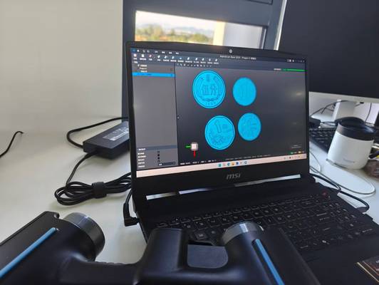
The true value of 3D scanning is realized in post-processing. INSVISION software guides point clouds through a structured sequence: automatic coordinate alignment with reference CAD models, generation of color deviation maps for immediate tolerance visualization, and one-click output of inspection reports.
For a machined bracket or an additive-manufactured insert, this workflow replaces manual measurement with a clear, visual verdict on whether critical surfaces are within spec. Verification of GD&T callouts against ASME Y14.5 standards happens within the same interface, producing digital reports that satisfy ISO 9001 documentation requirements.
This closed-loop process transforms raw data into actionable quality decisions, ready for internal review or customer submission.
Validating System Fit for Your Production Environment
A datasheet’s metrology-grade specifications do not guarantee on-site performance; shop-floor variables often dictate success. Before deploying an INSVISION solution, validate material reflectivity and thermal stability, as even advanced algorithms require consistent environmental baselines.
The AlphaScan series is engineered for applications like complex reverse engineering and first-article inspection, where its ability to generate detailed deviation maps accelerates multi-angle GD&T validation. While the integrated software facilitates seamless CAD alignment and reporting, the system delivers maximum ROI when paired with structured operator training for consistent data capture.
To scope a pilot, review your specific part dimensions, tightest tolerance bands, and line-side space constraints.
To assess if 3D scanning fits your verification challenges, consider your most common part materials, the size range of components, and your current reporting requirements for audit trails.
Hangzhou Insvision Technology Co.,Ltd.
Address: Building 1, No. 1399 Liangmu Road, Yuhang District, Hangzhou, Zhejiang 311121, China