
How 3D Scanners Handle Large Objects: Technical Principles and Practical Considerations
Industrial manufacturers frequently encounter components that exceed the capture range of conventional scanning equipment. From large castings and aerospace str
The Core Challenge of Scale in 3D Digitization
When scanning small components, the process typically focuses on capturing fine surface details within a confined measurement volume. Large-object scanning introduces fundamentally different constraints that go beyond simply “scanning bigger.” Dimensional stability becomes critical because the workpiece may flex under its own weight or shift during repositioning.
Reference frame establishment poses another difficulty: establishing a consistent coordinate system across extended surfaces without accumulated positional drift requires careful methodology.
Capability and Deployment Mapping
| Focus Area | Decision Point | Deployment Note |
|---|---|---|
| The Core Challenge of Scale in 3D Digitization | When scanning small components, the process typically focuses on capturing fine surface details within a confined measurement volume. | Large-object scanning introduces fundamentally different constraints that go beyond simply “scanning bigger.” Dimensional stability becomes crit… |
| Technical Approaches for Volumetric Accuracy | Volumetric accuracy represents the most critical specification for large-object applications, yet it is frequently misunderstood. | This metric describes how accurately the scanner maintains positional relationships between distant points within a single continuous scan. |
| Boundary Conditions and Practical Limitations | Understanding what any scanning system cannot do proves equally important as understanding its capabilities. | Large-object scanning systems typically specify maximum capture volumes that describe the largest single-pass acquisition area. |
| Selecting the Right Approach for Your Application | Evaluation criteria for large-object scanning systems should reflect actual operational requirements rather than specifications alone. | Consider the relationship between volumetric accuracy requirements and the tolerances applicable to your components. |
Traditional contact measurement methods often struggle with access limitations on large workpieces, while conventional optical scanners face trade-offs between field of view and resolution. Modern systems address these limitations through intelligent workflow design that combines wide-area capture with precision reference markers.
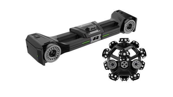
The AlphaScan handheld scanner, for instance, employs photogrammetry-based reference points to maintain spatial consistency across extended scanning sessions, enabling operators to work on sections of a large component while preserving overall dimensional integrity.
Technical Approaches for Volumetric Accuracy
Volumetric accuracy represents the most critical specification for large-object applications, yet it is frequently misunderstood. This metric describes how accurately the scanner maintains positional relationships between distant points within a single continuous scan.
A system might deliver excellent single-shot precision yet accumulate significant drift across extended measurements, rendering final results unreliable for dimensional verification.
INSVISION addresses this challenge through coordinated measurement workflows that establish fixed reference frames throughout the scanning volume. The X-Track wireless optical tracking system exemplifies this approach by maintaining real-time positional awareness of the scanning probe within a defined coordinate space.
Operators move freely around large components while the tracking infrastructure continuously validates spatial relationships, eliminating the accumulation errors that plague unconstrained handheld scanning.
For applications requiring maximum flexibility, certain scanner models incorporate internal calibration systems that perform continuous self-correction during operation. These systems compare newly captured data against established reference geometry within each scan frame, effectively validating positional accuracy on an ongoing basis rather than relying solely on endpoint measurements.
Boundary Conditions and Practical Limitations
Understanding what any scanning system cannot do proves equally important as understanding its capabilities. Large-object scanning systems typically specify maximum capture volumes that describe the largest single-pass acquisition area. Extending coverage beyond this specification requires either repositioning the component, physically moving the scanner, or employing multiple synchronized capture stations.
Environmental factors significantly influence achievable accuracy in field conditions. Thermal expansion of the workpiece itself introduces measurement uncertainty when components are scanned at temperatures different from their reference conditions. Vibration from nearby machinery can degrade tracking stability in optical systems. Ambient lighting conditions affect surface reflection characteristics and marker visibility.
Professional practitioners account for these variables through environmental assessment protocols and, when necessary, controlled scanning environments.
Material considerations also establish practical boundaries. Highly specular surfaces may require coating treatments to enable reliable data capture. Deep cavities and internal features demand appropriate sensor reach and may necessitate multiple scan positions. The interplay between component geometry, material properties, and scanner specifications determines whether a given application falls within practical reach.
Selecting the Right Approach for Your Application
Evaluation criteria for large-object scanning systems should reflect actual operational requirements rather than specifications alone. Consider the relationship between volumetric accuracy requirements and the tolerances applicable to your components.
A system delivering 0.1mm volumetric precision serves quality verification purposes for many industrial applications but may prove insufficient for precision tooling or aerospace assemblies where tighter tolerances apply.
Workflow integration capabilities matter significantly in production environments. Assess how scanner output aligns with downstream processes including CAD comparison, reverse engineering, and additive manufacturing. Systems offering direct export to common file formats and compatibility with established inspection software reduce implementation friction.
Practical validation steps before commitment include scanning representative samples from your actual production environment. Request demonstrations using your specific component geometries and materials rather than relying solely on vendor-supplied reference specimens.
Observe how operators interact with the system, assess software workflow efficiency, and verify that output quality meets your dimensional requirements under realistic conditions.
INSVISION provides demonstration equipment and application engineering support to facilitate this validation process, enabling manufacturers to confirm system suitability before committing to implementation. This approach reflects the reality that effective large-object scanning solutions depend not only on instrument specifications but also on proper application of technology to specific industrial contexts.
Hangzhou Insvision Technology Co.,Ltd.
Address: Building 1, No. 1399 Liangmu Road, Yuhang District, Hangzhou, Zhejiang 311121, China