

High-Volume 3D Inspection of Large Castings and Forged Parts: Adapting Scanning Strategy to Material, Geometry
Large castings, forged housings, and welded structural frames used in heavy machinery, marine propulsion, and energy equipment routinely exceed two meters in le
01 Object Characteristics and Inspection Pain Points
Large workpieces from foundries and forge shops share a common set of metrology challenges. The surfaces are often dark, oxidized, or sand-textured, which reduces the signal return of many laser scanners. Geometrically, the parts are defined by long sweeping curves, thick-to-thin transitions, and internal cavities that create self-occlusion.
On a hydro turbine runner, for example, the blade profiles are doubly curved and the root fillets are partially hidden. Cast valve bodies present deep bore intersections and flange faces that must be verified for flatness and angular tolerance. Sheet metal weldments in railcar frames exhibit spring-back and local distortion that can only be understood by comparing the as-built shape to the CAD nominal across the entire part.
Thermal history adds another layer: a large casting just removed from a cooling pit may still be drifting dimensionally, so the inspection window is tight and the measurement must be fast enough to capture one stable snapshot. Operators also need to avoid repeatedly repositioning the part, which would introduce alignment errors and consume crane time.
Selection Dimensions and Field Checks
| Focus Area | Decision Point | Deployment Note |
|---|---|---|
| 01 Object Characteristics and Inspection Pain Points | Large workpieces from foundries and forge shops share a common set of metrology challenges. | The surfaces are often dark, oxidized, or sand-textured, which reduces the signal return of many laser scanners. |
| 02 Scanning Strategy and On-Site Adaptation | A practical 3D scanning approach for large parts starts with a reference framework that is independent of the part itself. | The INSVISION X-Track wireless optical tracking system uses stereo vision to track the scanner’s position in real time, eliminating the need for… |
| 03 Data Processing, GD&T Evaluation, and Reporting | Once the point cloud is captured, the data is aligned to the part’s CAD model or to a reference coordinate system defined by datum features. | For large workpieces, alignment is rarely a simple best-fit; |
| 04 Equipment Considerations for Large-Scale 3D Inspecti… | When selecting a 3D scanning system for large workpieces, several factors influence whether the solution will work reliably on the shop floor. | Volumetric accuracy over a two-meter or three-meter range must be verified with a reference artifact, not just a datasheet value. |
02 Scanning Strategy and On-Site Adaptation
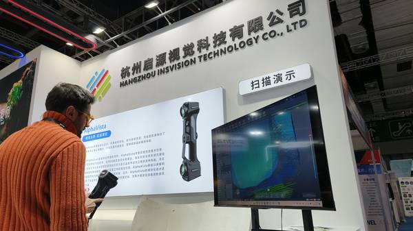
A practical 3D scanning approach for large parts starts with a reference framework that is independent of the part itself. The INSVISION X-Track wireless optical tracking system uses stereo vision to track the scanner’s position in real time, eliminating the need for target stickers that are hard to apply and remove on rough, oily surfaces.
The operator holds the AlphaScan handheld scanner and walks around the part, capturing complex geometry without the restriction of a fixed measurement arm. Dark foundry surfaces are handled by the scanner’s blue laser and adjustable exposure; the system can maintain high point density even on low-reflectivity cast iron. Deep pockets and bores are addressed by tilting the scanner and combining multiple view angles.
Instead of trying to capture every square millimeter in one pass, the scanning strategy segments the part into logical zones—reference datums, critical mating faces, and blend regions—and the X-Track system stitches them into a single coordinate frame.
This zone-based approach allows the inspector to prioritize high-tolerance areas while still getting a complete shape of the overall part, and it makes it possible to re-scan only a localized area if a repair is made later.
03 Data Processing, GD&T Evaluation, and Reporting
Once the point cloud is captured, the data is aligned to the part’s CAD model or to a reference coordinate system defined by datum features. For large workpieces, alignment is rarely a simple best-fit; the metrologist must decide which surfaces are functional and should be used to constrain the alignment, versus non-functional surfaces that can be allowed to float.
The software tools used with INSVISION systems support feature-based alignment, which lets the user pick bores, plane sections, and cylinder axes directly on the scan data. After alignment, a 3D color map comparison shows deviations across the entire part, making it immediately obvious where a casting has excess stock, where a flange has warped, or where a welded stiffener has pulled the plate.
Cross-sectional analysis of deep bores and long shafts can be extracted without cutting the part. The final report typically includes dimensional deviation plots, specific GD&T callout pass/fail status, and raw inspection data that can be archived for traceability.
Because the scan data is dense, the quality team can revisit the file months later and answer new questions—for example, checking a dimension that was not on the original inspection plan—without recalling the part.
04 Equipment Considerations for Large-Scale 3D Inspection
When selecting a 3D scanning system for large workpieces, several factors influence whether the solution will work reliably on the shop floor. Volumetric accuracy over a two-meter or three-meter range must be verified with a reference artifact, not just a datasheet value. The tracking system should be portable and quick to set up;
the X-Track system’s wireless connectivity and battery operation reduce cable clutter around heavy parts. The scanner’s ability to handle surface variation—from shiny machined pads to matte sand cast skin—determines how much operator intervention is needed during scanning. Weight and grip design of the handheld scanner matter because the operator will be holding it for extended periods while reaching around large structures.
The data pipeline is equally important: the software must handle large point clouds without excessive decimation that would mask fine surface defects.
INSVISION’s combination of the AlphaScan scanner and X-Track optical tracking addresses these points by providing a laser-based, target-free workflow that can be deployed directly in the manufacturing area, reducing the need to move heavy parts and enabling faster iteration between inspection, machining, and final acceptance.
Large workpieces will always present unique metrology demands, but the right scanning architecture turns a difficult inspection into a repeatable, data-rich process that supports both immediate quality decisions and long-term part family knowledge.
Hangzhou Insvision Technology Co.,Ltd.
Address: Building 1, No. 1399 Liangmu Road, Yuhang District, Hangzhou, Zhejiang 311121, China