

From Part Geometry to Inspection Reports: 3D scanning for automotive body panels
A body panel that looks right on the assembly jig can still produce a fender-to-door gap that flags under a 2.5 mm gauge, sends a hood leading edge too high, or
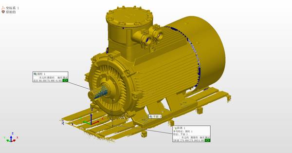
That is exactly the workflow that handheld 3D scanning, particularly with INSVISION’s AlphaScan system, enables for automotive body panels. The panels themselves range from deep-drawn steel door outers and aluminum hoods to injection-molded thermoplastic fascia and composite trunk lids.
What ties them together is a shared set of measurement challenges: large surface areas with compound curvature, thin-gauge sections that flex under clamping force, and Class A surfaces where reflectivity varies by material and coating.
Deployment Validation Checklist
| Focus Area | Decision Point | Deployment Note |
|---|---|---|
| Target part | Check size, surface condition, and key tolerances against the scan task | Run a full trial scan on a representative part |
| Data workflow | Verify point cloud, deviation map, and quality-report handoff | Confirm export formats and review ownership in advance |
| Shop-floor use | Review training, calibration, lighting, and working space | Keep the validation record as a repeatable inspection reference |
A stamped steel door skin fresh off the press can measure 1,100 mm across the diagonal, carry a clear zinc-phosphate coating, and show springback that shifts the character line by 0.3 mm across the middle third. Getting a full-field deviation map on that panel, in a timeframe that does not hold up the press line, is the practical problem that 3D scanning solves.
Surface Behavior and Measurement Obstacles Across Panel Types
Body panels present a mix of measurement obstacles that scale with material and forming process. Deep-drawn steel panels—door outers, quarter panels, roof skins—tend toward high stiffness at the flanges and softer compliance in the middle where the sheet thins during forming.
The trim edge and hem flange are the datums that locate the panel in the assembly fixture, but the area between them is what the eye sees, and that is where springback concentrates.
Aluminum panels, common on hoods and decklids, add a second variable: the surface is more reflective under structured-light scanning, and the part is more prone to handling deformation if the scanning fixture does not match the panel’s gravity orientation. Thermoplastic fascia—front and rear bumper covers, rocker moldings, grille surrounds—throw another curve.
The surface is often dark, textured, or painted with a low-gloss coating that can absorb or scatter projected light patterns. The part is compliant enough that even contact-based measurement risks denting the surface, and the mounting scheme on the vehicle relies on snap tabs and locator pins that do not replicate the inspection datum easily.
Key Points at a Glance
- Body panels present a mix of measurement obstacles that scale with material and forming process.
- The scan strategy for a body panel starts with the question of how the part is held during measurement.
- The value of the scan is realized in the deviation analysis, not in the raw data.
- For production-quality monitoring, the scan must be repeatable not only in accuracy but in procedure.
For all these materials, the common requirement is a measurement density that far exceeds what a CMM or even a laser tracker can deliver in a practical cycle time. A door outer panel needs surface points spaced at roughly 2 mm to capture the transition from the crown to the character line with enough resolution to feed a tryout loop.
The AlphaScan handheld scanner delivers that density by projecting a fine blue laser line array and capturing up to 1.6 million points per second, maintaining a measurement accuracy of 0.02 mm under controlled conditions. That point density is what makes it possible to evaluate not just maximum deviation but the local curvature gradient that drives optical quality on a painted panel.
Structuring the Scan Around Fixturing, Features, and Reference Geometry
The scan strategy for a body panel starts with the question of how the part is held during measurement. A panel that is fixtured at its hem flange and checked under its own weight will produce a different deviation map than the same panel resting on a soft support.
The preferred approach is to fixture the part in a configuration that matches the body-in-white locator scheme—net pads at the hem, a pin and slot at the locating holes, and gravity orientation that matches the car position on the line.
Where a dedicated checking fixture is not available, the part can be scanned on a rigid, non-marring fixture bed, and the alignment reference can be built from the CAD datums rather than the fixture itself.
Once the part is stable, the AlphaScan operator captures the full outer surface in a continuous pass, moving across the panel in overlapping stripes. The scanner’s algorithm tracks surface geometry in real time, so no target stickers are needed on the panel itself—a significant advantage on Class A surfaces where adhesive residue or marker dots are unacceptable.
For feature-rich areas such as the license plate depression, the door handle nest, and the styling scallop, the scan path tightens to capture the steeper draft angles and the small radii at the bottom of each feature.
The raw point cloud is then aligned to the CAD model using a best-fit registration on the datum surfaces—hem flange, locator holes, and the primary mating edge—leaving the free-form surfaces unconstrained so deviation can be measured independently.
From Point Cloud to Actionable Report: CAD Comparison and Tolerance Zones
The value of the scan is realized in the deviation analysis, not in the raw data. After alignment, the software computes a 3D color map that plots the signed distance between the scanned surface and the CAD model at every point. For a hood outer panel, a typical tolerance zone might be ±0.5 mm across the main surface, tightening to ±0.3 mm within 30 mm of the fender and headlamp cut lines.
The color map immediately shows whether the deviation is distributed as a uniform offset—suggesting a springback compensation issue—or as a localized dip near the inner panel bond line that points to a heat distortion problem during curing.
The report output from the INSVISION workflow includes the overall deviation histogram, pass/fail callouts against the tolerance template, and section slices at any location the engineer specifies. For a door inner panel, a section through the hinge mounting face and the latch face is essential; the two planes must be parallel within 0.15 mm across their full span, or the door will drop during assembly.
The scan data also feeds a GD&T evaluation of surface profile, which replaces the traditional grid of discrete CMM points with a continuous surface check. The software exports the point cloud in standard formats that can be read directly into the tooling team’s CAD system for die compensation, eliminating the step of manually interpreting a CMM table and guessing what the surface is doing between the measured points.
Building a Repeatable Inspection Loop Across Batch Production
For production-quality monitoring, the scan must be repeatable not only in accuracy but in procedure. The same scan path, the same alignment references, and the same reporting template must be applied from the first tryout panel through the production run.
INSVISION’s software supports a template-based inspection routine where the scan steps, alignment parameters, and tolerance zones are saved and recalled for each panel style. An operator loads the template, scans the panel, and receives a pass/fail indication along with the full deviation map in minutes.
This routine becomes especially useful when multiple panel variants run through the same press line. A door outer for a long-wheelbase version may share the front half of the stamping with the standard model but differ in the rear cut line and the character line sweep. By maintaining separate inspection templates for each variant, the quality team can switch between them without re-engineering the measurement plan.
The scan data from each batch is archived with the batch number, press stroke counter, and material lot, creating a digital history that can be mined for trend analysis.
When a new batch of aluminum blanks shows a slight increase in springback, the deviation map makes the shift visible before the panels reach the assembly line, and the stamping team can adjust the draw bead settings or the blank holder force before the next coil runs. The result is a measurement loop that feeds directly into process control, turning body panel inspection from a gate check into a real-time manufacturing input.
Hangzhou Insvision Technology Co.,Ltd.
Address: Building 1, No. 1399 Liangmu Road, Yuhang District, Hangzhou, Zhejiang 311121, China