
Closing the Metrology Gap with AlphaScan 3D Scanning in Industrial Quality Workflows
Discover how INSVISION AlphaScan 3D scanning bridges the gap between measurement hardware and CAD data in industrial quality workflows, reducing errors and speeding up inspection.
The Real-World Challenge: From CAD to Shop Floor Without Data Loss
A typical first-article inspection or in-process quality check on a medium-sized casting or welded assembly follows a predictable path. The part arrives at the quality lab or a benchtop station on the production floor. A CMM or manual gauge setup captures discrete points. The operator then transfers those measurements to a report, often re-entering nominal values and tolerance bands from a separate drawing or CAD viewer.
When deviations are found, the root cause analysis requires overlaying measured data from 3D scanning onto the original 3D model — a step that frequently involves exporting, converting, and re-aligning files across multiple software packages.
Capability and Deployment Mapping
| Focus Area | Decision Point | Deployment Note |
|---|---|---|
| The Real-World Challenge: From CAD to Shop Floor Withou… | A typical first-article inspection or in-process quality check on a medium-sized casting or welded assembly follows a predictable path. | The part arrives at the quality lab or a benchtop station on the production floor. |
| This workflow introduces three persistent pain points: | For a tier-1 supplier running three shifts, a measurement process that requires dedicated fixturing or a fixed CMM cell adds another layer of complex… | Moving parts to a centralized lab creates a bottleneck, while dedicating a station to a single part family is rarely economical when product mix… |
| Designing a Measurement Workflow That Mirrors the Produ… | The alternative is a measurement architecture that treats the CAD model as the single source of truth from the start. | Instead of scanning first and aligning later, the system imports the native CAD file — STEP, IGES, or Parasolid — along with its associated 2D d… |
This workflow introduces three persistent pain points:
- GD&T re-entry errors. Tolerance callouts defined in the CAD model are manually transcribed, creating opportunities for mismatch between the design intent and the inspection record.
- Alignment drift. Without a unified coordinate system that persists from scan to report, comparing multiple parts or tracking wear over a production run becomes inconsistent.
- Setup overhead on complex geometries. Deep pockets, freeform surfaces, and thin-walled sections demand multiple scan passes and repositioning, which eats into the available inspection window on a busy line.
For a tier-1 supplier running three shifts, a measurement process that requires dedicated fixturing or a fixed CMM cell adds another layer of complexity. Moving parts to a centralized lab creates a bottleneck, while dedicating a station to a single part family is rarely economical when product mix changes weekly.
Designing a Measurement Workflow That Mirrors the Production Reality
The alternative is a measurement architecture that treats the CAD model as the single source of truth from the start. Instead of scanning first and aligning later, the system imports the native CAD file — STEP, IGES, or Parasolid — along with its associated 2D drawings and GD&T annotations. The scan data is then registered directly to that model, preserving every tolerance callout without manual transcription.
This approach shifts the inspection sequence:
- Import and prepare. The quality engineer loads the design data into the inspection platform once. All GD&T references are extracted automatically.
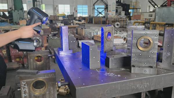
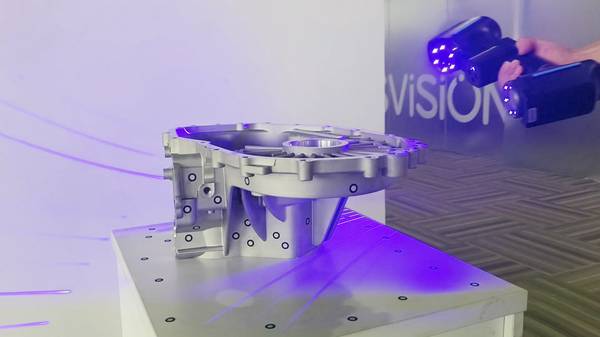
- Scan at the point of use. A handheld 3D scanner is brought to the part, not the other way around. No fixed mounting infrastructure is required.
- Live alignment and deviation mapping. As the operator sweeps the scanner across the surface, the software displays a real-time color map of deviations against the CAD nominal.
- One-click reporting. The final report inherits the same tolerance
Hangzhou Insvision Technology Co.,Ltd.
Address: Building 1, No. 1399 Liangmu Road, Yuhang District, Hangzhou, Zhejiang 311121, China