
AlphaScan’s 3D Scanning Workflow Brings Lab-Grade Metrology to the Production Floor
Discover how INSVISION's AlphaScan 3D scanning workflow brings lab-grade metrology to the production floor, capturing full-field geometry with high accuracy.
INSVISION built the AlphaScan handheld scanner to answer that pressure directly. With a 30/42 blue laser line configuration — 22/34 cross lines for rapid area coverage and a single dedicated fine line for edges, deep pockets, and tight radii — and proprietary AI‑driven reconstruction algorithms, AlphaScan delivers a dense, inspection‑ready mesh in real time.
The system holds volume accuracy of 0.015 mm + 0.025 mm/m through global coordinate alignment, eliminating the drift that plagues sequential scanning. The result is a 3D scanning workflow that moves measurement from a lab‑bound project to a shop‑floor process step.
The Inspection Bottleneck on the Shop Floor
Traditional metrology tools force a trade‑off. A fixed CMM provides point‑based accuracy but lives in a climate‑controlled lab. Every part must be transported, staged, and measured on someone else’s schedule. Laser trackers handle large volumes yet struggle with intricate features like blend radii or deep pockets.
Manual calipers and micrometers capture a handful of discrete dimensions — useless for characterizing an organic turbine blade root or an injection‑molded housing with draft angles and complex curvature.
Capability and Deployment Mapping
| Focus Area | Decision Point | Deployment Note |
|---|---|---|
| The Inspection Bottleneck on the Shop Floor | Traditional metrology tools force a trade‑off. | A fixed CMM provides point‑based accuracy but lives in a climate‑controlled lab. |
| A Workflow Designed for Speed and Fidelity | AlphaScan’s end‑to‑end 3D scanning workflow runs in four sequential steps, each engineered to remove friction from industrial measurement. | Confirm against part conditions, inspection tempo, and data-output requirements. |
| From Scan to Report: How the Workflow Unfolds in Practi… | Consider a cast brake caliper housing with no surviving CAD model. | Its sweeping organic surfaces make touch‑probe measurement a slow exercise in connecting sparse points. |
| Where AlphaScan Fits the Industrial Floor | The table below maps AlphaScan’s core capabilities | Confirm against part conditions, inspection tempo, and data-output requirements. |
The hidden cost isn’t the equipment price tag; it’s the idle time while parts queue for inspection and the risk of shipping a latent form error because point‑based tools missed the full surface story. For parts that are large, heavy, permanently installed, or geometrically complex, moving the part costs more than the measurement itself.
Aerospace tooling, energy castings, automotive body‑in‑white assemblies — these demand an industrial 3D scanning workflow that walks to the part, captures complete surface data, and delivers actionable GD&T results without a lab backlog.
A Workflow Designed for Speed and Fidelity
AlphaScan’s end‑to‑end 3D scanning workflow runs in four sequential steps, each engineered to remove friction from industrial measurement.
- Pre‑scan scale placement. The operator positions calibrated scale bars with coded targets across the part or fixture. No fixed installation, no custom fixturing, no lengthy alignment routines. Two photography measurement scales in a simple vertical or herringbone pattern establish a traceable reference frame in seconds.
- Scanner initialization and global coordinate alignment. AlphaScan recognizes the targets instantly and locks onto a high‑precision global coordinate system. This eliminates accumulated drift across multiple scan segments, maintaining volume accuracy at 0.015 mm + 0.025 mm/m. Manual alignment errors disappear before scanning begins.
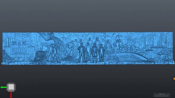
- Segmented data capture. The engineer scans the part in manageable sections. The scanner continuously tracks global markers, stitching each patch into the unified coordinate frame without overlapping errors. Operators switch on‑demand between standard, deep hole, and fine scan modes to match part geometry mid‑task. The 650 mm × 550 mm scan area covers medium components fast, and the balanced handheld design supports shift‑long scanning without fatigue‑inducing data degradation.
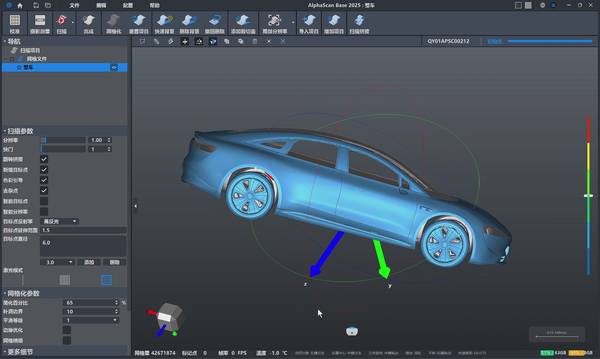
- Integrated post‑processing. Captured data flows directly into INSVISION’s PTB‑certified 3D software. GD&T callouts, CAD‑to‑part deviation color maps, and automated reports are generated inside a single environment. No third‑party conversion delays, no re‑import loops. The software exports to all mainstream CAD and 3D formats, and can produce ASME Y14.5‑compliant inspection documents accepted in PPAP submissions.
From Scan to Report: How the Workflow Unfolds in Practice
Consider a cast brake caliper housing with no surviving CAD model. Its sweeping organic surfaces make touch‑probe measurement a slow exercise in connecting sparse points. With AlphaScan, the entire surface is captured in one continuous scan session. The dense mesh feeds directly into reverse engineering software, delivering a watertight model ready for toolpath generation.
The workflow — scan, align, compare, report — replaces hours of manual point collection with a process that keeps the production line moving.

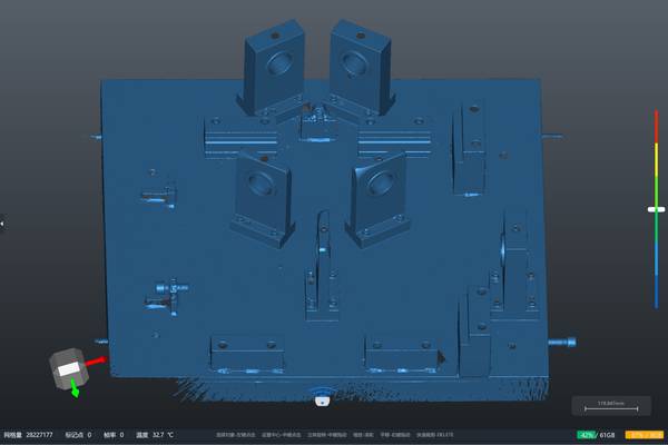
The same connected workflow repeats across other industrial scenarios. For injection mold inspection on high‑reflective tool steel, the blue laser projector cuts through the noise that scatters red laser light. A mold maker scans the cavity immediately after polishing, right at the bench.
The live CAD deviation map flags undercuts or wear in real time, with a tolerance band of ±0.05 mm showing green and anything drifting toward yellow or red triggering a closer look. The engineer rotates aligned datasets, slices sections, and measures specific features without exporting to another package. Reporting generates an inspection document the customer accepts as part of the PPAP submission.
In additive manufacturing pre‑processing, a bracket printed in AlSi10Mg on a powder bed fusion machine comes off the plate and goes straight under the scanner. AlphaScan captures the as‑built surfaces in minutes, and the software compares them to the original STL. Warpage or excess stock shows up immediately. The data feeds back into build preparation software, allowing compensation for the next print.
No one guesses whether the part will clean up in post‑machining; the scan data confirms it.
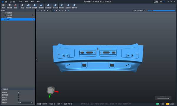
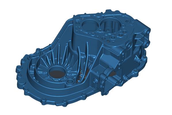
For small‑to‑medium part batch inspection — hydraulic manifold blocks, gearbox housings — the repetitive scanning workflow compounds time savings. A fixture holds the part, a predefined scanning routine runs with the same alignment references, and the operator only moves the scanner. The software automatically aligns each new scan to the master CAD and updates the deviation report.
Per‑part measurement cycle time drops because there is no reprogramming, no manual data transfer, and no waiting for a climate‑controlled lab.
Where AlphaScan Fits the Industrial Floor
The table below maps AlphaScan’s core capabilities
Hangzhou Insvision Technology Co.,Ltd.
Address: Building 1, No. 1399 Liangmu Road, Yuhang District, Hangzhou, Zhejiang 311121, China