

Matching 3D Vision Inspection Solution Types to Industrial Tasks
3d vision inspection: Core Industrial Use Cases for 3D Vision Inspection Core Industrial Use Cases for 3D Vision Inspection The shift toward closed-loop.
Core Industrial Use Cases for 3D Vision Inspection
The shift toward closed-loop quality data has changed how manufacturers deploy 3D vision inspection. Rather than existing as an isolated measurement island, these systems now feed directly into lean continuous improvement programs and Industry 4.0 connected quality workflows. A dimensional deviation captured at the line can trigger root-cause analysis upstream within the same shift, not after a batch has already shipped.
Common Questions
What should teams check when evaluating Core Industrial Use Cases for 3D Vision Inspection?
The shift toward closed-loop quality data has changed how manufacturers deploy 3D vision inspection.
Deployment Validation Checklist
| Focus Area | Decision Point | Deployment Note |
|---|---|---|
| Target part | Check size, surface condition, and key tolerances against the scan task | Run a full trial scan on a representative part |
| Data workflow | Verify point cloud, deviation map, and quality-report handoff | Confirm export formats and review ownership in advance |
| Shop-floor use | Review training, calibration, lighting, and working space | Keep the validation record as a repeatable inspection reference |
What should teams check when evaluating Key Constraints That Shape 3D Vision Inspection Solution Fit?
In the last five years, 3D vision inspection has moved from a specialized lab tool into production environments where it now competes with traditional CMM and hard-gauge workflows.
What should teams check when evaluating 3D Vision Inspection Solution Categories and Task Alignment?
Before a line starts moving or a first-article report gets signed off, the real decision is matching the inspection method to the part, the environment, and the repeatability the…
Task requirements, not sensor specs, drive solution selection. Four primary task classes dominate Western manufacturing deployments. First-article inspection uses 3D vision inspection to validate GD&T callouts before production ramps, common in automotive OEM body-in-white programs where fixture validation and datum alignment matter more than raw point density.
In-process dimensional verification addresses aerospace MRO component wear assessment, where blade airfoil geometry must be checked against allowable service limits without disassembly delays. Large-assembly alignment checks support energy turbine manufacturing, confirming stage-to-stage positioning across meter-scale components.
High-volume inline conformity screening handles medical device implant surface and tolerance validation, where batch repeatability and takt time constrain every measurement cycle.
A persistent misconception holds that 3D vision inspection replaces tactile CMMs outright. In practice, these technologies complement each other. Structured light and laser-based 3D vision excel at dense surface capture and rapid comparative analysis. Tactile probing still wins for deep bores, hidden features, and traceable sub-micron verification.
INSVISION industrial 3D scanners fit best where the task demands fast surface digitization, CAD comparison, or repeatable inline checks on parts with accessible geometry. Match the tool to the measurement problem, not the other way around.
Key Constraints That Shape 3D Vision Inspection Solution Fit
In the last five years, 3D vision inspection has moved from a specialized lab tool into production environments where it now competes with traditional CMM and hard-gauge workflows. That shift has forced a more disciplined conversation about solution fit. The same scanner that works beautifully on a granite table in a metrology lab can struggle under skylights, vibration, or mixed-part flow on an assembly floor.
What has changed is not just sensor capability but the way integrators and quality teams now decompose an inspection task into engineering constraints before evaluating hardware. This section breaks down five of those constraints. They are not product specifications. They are the boundary conditions that determine whether a given 3D vision inspection approach will hold up in your specific application.
Part size range is the first filter. Sub-centimeter medical components demand a different optical setup than multi-meter aerospace structures. A scanner configured for a turbine blade root will not resolve fine features on a bone screw, just as a small-field system will require excessive stitching across a wing skin. Working distance, field of view, and depth of field all scale with part envelope.
INSVISION addresses this through task-matched scanner configurations rather than a single general-purpose device, but the routing decision starts with the largest and smallest features you must resolve, not the average part.
Site freedom is often underestimated. A fixed lab with controlled temperature and vibration isolation is one environment. An on-site assembly floor or field MRO setting is another. Ambient lighting changes, dust, operator traffic, and floor vibration all influence measurement stability. Some 3D vision inspection systems tolerate these conditions better than others, but no system eliminates them.
The question is whether your site allows you to control the environment or whether the equipment must tolerate it. This single constraint often determines whether a portable scanner or a fixed-cell solution makes more sense.
Marker compatibility matters more than many buyers expect. Some parts can be lightly sprayed or dotted with reference markers without consequence. Others, such as finished medical implants or Class A automotive surfaces, cannot. Marker-free workflows rely more heavily on surface geometry and texture, which means shiny, featureless, or highly uniform parts become difficult.
If your part mix includes polished or painted surfaces, you should test marker-free performance on your actual finish, not on a matte reference coupon.
Takt time is the constraint that separates offline inspection from inline use. If you have forty-five seconds per station, the solution must acquire, register, and evaluate data within that window. If you have four hours for a first-article inspection, the priorities shift toward density and completeness. 3D vision inspection can serve both, but the system architecture changes.
High-speed production lines usually require fixed mounting, triggered acquisition, and automated pass-fail logic. Low-volume inspection allows more manual interaction and deeper analysis.
Batch repeatability is the last major routing criterion. High-volume mass production rewards systems that are configured once and run thousands of cycles with minimal operator input. Low-volume custom parts, common in aerospace MRO or tooling, require frequent program changes and flexible part positioning. The same hardware may work in both cases, but the software workflow and operator skill requirements differ significantly.
Beyond these five, several boundary conditions quietly determine real-world performance. Ambient lighting can wash out laser lines or confuse stereo matching. Surface finish variability, from machined to as-cast to painted, changes how light returns to the sensor. Operating temperature ranges affect both sensor stability and part dimensions.
INSVISION systems are specified for practical industrial conditions, but any 3D vision inspection deployment should include a short on-site validation using your actual parts, finishes, and cycle timing before committing to a full integration.
3D Vision Inspection Solution Categories and Task Alignment
Before a line starts moving or a first-article report gets signed off, the real decision is matching the inspection method to the part, the environment, and the repeatability the job demands. A casting that weighs 200 kg does not get inspected the same way as a stamped bracket cycling every 14 seconds. The four categories below are not performance tiers. They are workflow fits.
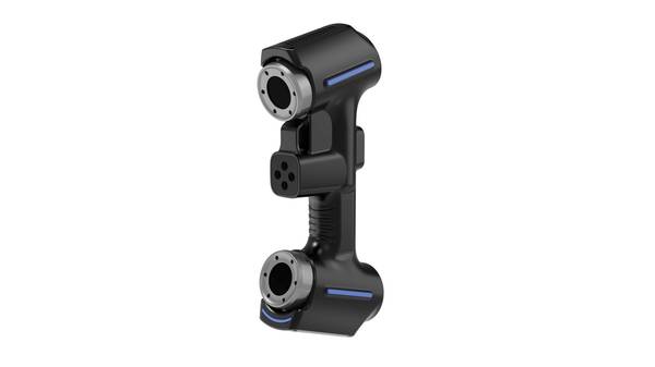
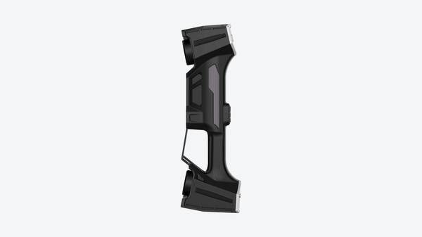
Portable handheld 3D vision systems work best when the part cannot move or the inspection happens at the tool, fixture, or machine. Structured light and laser triangulation capture surface geometry directly, which suits first-article checks, tooling validation, and spot troubleshooting on large or awkward components. The operator moves the scanner; the part stays put.
This is the natural choice for maintenance crews and quality engineers who need answers in minutes, not days.
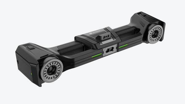
Large-volume tracking-based 3D inspection systems address a different constraint: part size and reference stability. Photogrammetric tracking establishes a coordinate frame around objects measured in meters, not millimeters. Aerospace MRO work, large weldments, and assembly-level verification often fall into this category. The scanner tracks against markers or features, so local movement matters less than global alignment.
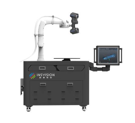
Automated fixed-cell 3D inspection systems remove operator variability. The part arrives at a known position, the sensors run a defined program, and the software compares the point cloud to CAD or GD&T callouts. Batch repeatability and takt time drive this selection. If the same five dimensions need checking on 2,000 parts a month, a fixed cell makes more sense than a handheld scanner.
Inline robotic 3D inspection systems push the same logic into the production line. The sensor rides on a robot or gantry, triggers on part presence, and feeds results directly to quality management software. High-volume automotive and medical device lines use this approach when inspection cannot become a bottleneck.
INSVISION’s industrial 3D vision inspection portfolio spans all four categories. The design emphasis is consistent: rugged factory environments, traceability aligned with ISO/ASME measurement practices, and data output compatible with common CAD and quality management formats.
That matters less in a demo than it does six months into production, when the scanner has to survive coolant mist, vibration, and a third-shift operator who has never seen the manual.
Validating Solution Fit Through Structured Sample Testing
The core value of structured sample testing is that it removes guesswork before capital is committed. For a 3D vision inspection system, a spec sheet tells you what the hardware can do under ideal conditions.
It does not tell you whether the system can hold a true position tolerance on a cast aluminum bracket with mill scale still on the datum pads, or whether ambient vibration from a nearby conveyor will degrade point cloud density. The only way to know is to run your parts, under your conditions, through the actual inspection workflow.
Start by defining what matters. Pull the critical-to-quality characteristics from the drawing: the GD&T callouts, the tolerance bands, the surface finish requirements. If a bore diameter has a plus or minus 25 micron band, the validation test must measure that exact bore on multiple samples, not a similar feature on a different part number.
Tolerance bands dictate sensor selection, standoff distance, and the number of scan passes required. A loose profile tolerance on a large weldment is a very different problem than a tight runout tolerance on a machined shaft. Write these requirements down before any hardware arrives.
Part samples are the second variable. The samples you send for validation must reflect production reality. If your castings arrive with flash, draft, and variable surface oxidation, do not send a clean machined prototype. The 3D vision inspection system must handle the worst-case surface finish, not the best-case. Include at least two or three samples per part number to capture normal process variation.
One sample only proves the system worked once. Multiple samples show repeatability across the batch.
Environmental conditions matter more than most buyers expect. A 3D vision inspection cell that works in a clean metrology lab may struggle on a shop floor with 35 degree heat, oil mist, or overhead lighting that changes between shifts. Run the validation test in the actual location where the system will live, or as close to it as possible. If the system will sit next to a stamping press, test it next to a stamping press.
If operators will load parts by hand, have operators load parts during the test. These factors affect scan quality, cycle time, and long-term reliability.
Data output is the step people skip. A 3D vision inspection system produces point clouds and mesh data. Your quality team probably works in CAD comparison software, SPC packages, or an MES platform. Before you sign off on a system, confirm that the exported data flows into those tools without manual rework. Test the full path: scan, process, export, import, report.
If the system exports a point cloud but your SPC software expects a CSV of measured values, someone will be doing manual data entry every shift. That erodes the value of the investment quickly.
INSVISION provides application engineering support to lead these validation tests. The team works from your part drawings, your tolerance requirements, and your production environment to structure a test that answers the right questions. For custom or high-stakes inspection tasks—aerospace MRO, medical device, automotive first-article inspection—generic spec comparisons are not enough.
Sample testing is the most reliable way to confirm a 3D vision inspection solution will perform where it matters: on your parts, in your plant, feeding your quality system.
Actionable Decision Checklist for 3D Vision Inspection Investments
Are you buying a 3D vision inspection system for the problem in front of you, or for the problem you will have in three years? That question matters more than any single specification on a datasheet. The following checklist consolidates the evaluation criteria most likely to determine whether a system actually works on your floor. Work through it before you shortlist hardware.
Part size range requirements
Define the smallest feature you must resolve and the largest surface you must cover in one setup. A system configured for meter-class composite panels will not resolve a 0.5 mm casting defect, and a tight-field scanner will be painfully slow on large weldments. Confirm the working volume covers your largest part with room for fixturing. If you run multiple part families, map the full envelope, not the average part.
Intended use environment
Lab, factory floor, or field work each impose different constraints. A lab system can tolerate tripods, controlled lighting, and stable temperature. A floor system next to a machining cell has to survive vibration, dust, and occasional coolant mist. Field inspection for aerospace MRO or energy assets adds portability, battery operation, and sunlight.
Ask the vendor where the system is actually rated to operate, not where it was demonstrated.
Marker application feasibility
Some 3D vision inspection workflows require markers or texture on the part surface. If you are inspecting polished turbine blades, painted automotive panels, or safety-critical surfaces, marker application may be unacceptable. If you can mark parts, determine whether the marker pattern survives cleaning, handling, and process fluids. This single constraint often eliminates entire technology categories.
Required inspection cycle time
Takt time is non-negotiable on a production line. A system that produces beautiful data in four minutes is useless if your line moves every 90 seconds. Break the cycle into scan time, processing time, and report generation. Confirm whether processing can run in parallel with the next scan. If you need in-line 3D vision inspection, the software pipeline matters as much as the sensor.
Production batch volume
High-mix, low-volume work demands fast changeover and minimal programming. High-volume, low-mix work rewards fixed automation and repeatable fixtures. Be honest about how often you will reconfigure the system. A solution optimized for a single part number will frustrate a job shop; a flexible system may be overkill for a dedicated line.
Scalability and integration
Look beyond the initial task. Can the system integrate with robotic automation for automated loading or scanning paths? Can it expand to larger assembly sizes without replacing core components? Does it connect to Industry 4.0 quality data platforms, MES, or SPC software? Systems that lock inspection data in a closed file format create downstream integration costs.
INSVISION industrial 3D scanners are built to support these forward-looking requirements, with interfaces and data formats that fit modern quality data pipelines rather than forcing manual export workarounds.
The most effective 3D vision inspection investments are matched directly to task constraints and long-term operational goals, not selected on generic performance metrics. A scanner with impressive accuracy numbers in a lab demo can fail on a factory floor if the environment, part geometry, or cycle time were never honestly evaluated. Work the checklist first. Then look at hardware.
Hangzhou Insvision Technology Co., Ltd.
Address: Building 1, No. 1399 Liangmu Road, Yuhang District, Hangzhou, Zhejiang 311121, China
Copyright © Hangzhou Insvision Technology Co., Ltd. All rights reserved.
Copyright © Hangzhou Insvision Technology Co., Ltd. All rights reserved.