

Why Single-Spec Laser Scanning Claims Fail Industrial Quality Validation
laser scanning: The Widespread Assumption That One Spec Defines Laser Scanning Performance The Widespread Assumption That One Spec Defines Laser Scanning.
The Widespread Assumption That One Spec Defines Laser Scanning Performance
Quality and engineering teams in Western manufacturing often shortlist laser scanning systems by a single published number—nominal accuracy or advertised scan speed. It feels efficient. Procurement frameworks reward easily comparable specs, and early 3D scanning marketing leaned hard on headline metrics. The habit stuck.
Scenario Snapshot
A practical way to read the article is through this scenario:
- The Widespread Assumption That One Spec Defines Las…: Quality and engineering teams in Western manufacturing often shortlist laser scanning systems by a single publishe…
- Why Single-Spec Laser Scanning Evaluations Collapse…: A scanner that passes a lab demo can still fail the moment it reaches a production cell.
- Evidence-Based Validation Checks For Industrial Las…: Quality teams rarely get useful answers from a single specification line.
But the assumption carries real risk. An automotive tier 1 evaluating sheet metal inspection tools might lock onto accuracy without asking how the scanner handles edge definition on thin-gauge panels. An aerospace MRO team measuring turbine components may prioritize speed, then discover the fast mode cannot resolve tight internal features.
Deployment Validation Checklist
| Focus Area | Decision Point | Deployment Note |
|---|---|---|
| Target part | Check size, surface condition, and key tolerances against the scan task | Run a full trial scan on a representative part |
| Data workflow | Verify point cloud, deviation map, and quality-report handoff | Confirm export formats and review ownership in advance |
| Shop-floor use | Review training, calibration, lighting, and working space | Keep the validation record as a repeatable inspection reference |
Medical device manufacturers validating implant quality systems under FDA and ISO 13485 requirements face yet another layer: the spec sheet says nothing about whether scan data holds up under audit.
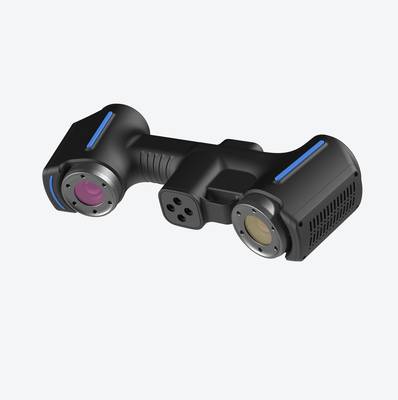
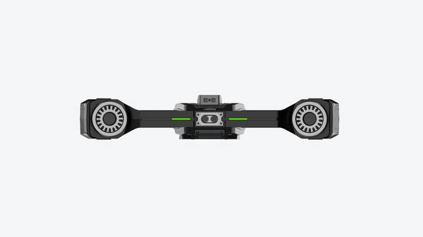
When the tool doesn’t match the actual GD&T callouts, surface finish, or feature size, you get non-compliant inspection records, production bottlenecks, or scrap you didn’t budget for. One number cannot carry that weight. INSVISION scanners, for example, operate in multiple modes—deep hole scanning with a single blue laser line, precision scanning with 7 lines, or high-speed modes with 26 or 50 lines depending on the unit.
That matters because the same system must adapt to different tasks, not just hit one idealized measurement condition.
Why Single-Spec Laser Scanning Evaluations Collapse On The Shop Floor
A scanner that passes a lab demo can still fail the moment it reaches a production cell. I have watched quality teams sign off on a system based on a single accuracy figure, only to find the same unit struggling on a turbine housing with a deep bore, or drifting when a stamping press fires two bays over. The spec sheet was not wrong. It just did not survive contact with the actual boundary conditions.
Part geometry is usually the first thing that breaks the comparison. Components in energy and aerospace work rarely look like the calibration blocks used in vendor testing. Deep holes, undercuts, and reflective weld-prep surfaces all change how laser scanning behaves in practice.
A system may advertise strong lab-measured precision, but if the effective scan coverage drops on a thin-walled diffuser or a polished bearing journal, the inspection cycle slows and the data gets patchy. INSVISION scanners address this through selectable scanning modes, including a single blue laser line for deep-hole access alongside precision modes using multiple blue laser lines.
That matters because the operator can switch strategies for the geometry in front of them, rather than forcing one mode to do everything. Delicate composite finishes create another constraint. Aggressive scan settings that work on cast iron can leave a carbon-fiber skin flagged with false surface noise, and the quality lead ends up chasing defects that are not there.
Shop floor conditions are the second failure point, and in my experience they are the least appreciated during vendor selection. A metrology lab is quiet, temperature-stable, and free of forklift traffic. A 24/7 manufacturing plant is none of those things. Temperature swings shift both the scanner and the part.
Vibration from adjacent CNC equipment or conveyor drives introduces low-level movement that degrades point cloud stability. Ambient lighting, especially overhead LED arrays or sunlight through dock doors, can interfere with optical capture. None of this shows up in a controlled ISO 17025 environment. For a quality lead maintaining accreditation, the relevant question is not whether the scanner works in a lab.
It is whether the results remain defensible when the building moves. INSVISION systems are built for field-style manufacturing use, with blue laser technology that resists ambient light interference better than older red-laser approaches. That is a practical advantage, not a marketing line, when the scan has to happen next to a running machining center.
The third collapse point is workflow integration. A scanner can capture points quickly in a demo, then slow the entire inspection process if the output does not fit the existing CAD, QMS, or digital thread tools. I have seen companies buy a high-speed system and then discover that every scan requires manual reformatting before it can be compared against the CAD model or archived in the QMS.
That manual step eats more time than the scan saves. Teams working to ASME Y14.5 GD&T callouts need scan data that aligns cleanly with datum structures and tolerances, not raw point clouds that require hours of cleanup. Industry 4.0 initiatives make this worse. If the scanner cannot feed a digital twin or a paperless inspection workflow without custom scripting, it becomes an island.
The evaluation should include a sample part run through the complete process: scan, mesh, align, extract features, export to the QMS. If any step requires manual rework, the advertised scan speed is irrelevant.
These are not rare edge cases. Deep bores, reflective surfaces, vibration, temperature drift, and CAD alignment issues are daily realities in high-volume manufacturing. A single-spec evaluation hides all of them. The better approach is to test on your own worst part, in your own environment, with your own downstream workflow. That is where laser scanning either proves itself or falls apart.
Evidence-Based Validation Checks For Industrial Laser Scanning Tools
Quality teams rarely get useful answers from a single specification line. A vendor can quote volumetric accuracy on a calibration block all day, but that tells you almost nothing about how the tool handles a cast housing with deep bores, a machined sealing face with a 0.05 mm flatness callout, or a shiny turned diameter that wreaks havoc on optical systems.
The only way to know whether industrial laser scanning equipment fits your operation is to run structured, reviewable validation against your own parts and workflows.
INSVISION addresses this directly by supporting a validation approach built around three audit-ready steps. Each step produces documented evidence, not anecdotes, so the results can be presented to leadership or external auditors without hesitation.
Start with production part validation. Skip the standardized artifact. Pull an actual production component that carries the features your team fights with every week: tight GD&T callouts, mixed surface finishes, deep hole geometry. Scan that part and compare the output against known reference data from your existing CMM or hard gaging.
This reveals edge behavior that a calibration block never will, including how the scanner handles edges, steep draft angles, and reflective surfaces at the exact orientations your parts present. If the system cannot hold tolerance on a feature your customer inspects regularly, you need to know before it lands on the floor.
Move next to end-to-end workflow testing. Raw scan speed is marketing; cycle time is engineering. Time the complete sequence: part setup, scan, data alignment, mesh processing, report generation, and export to your quality software. A scanner that captures data quickly but forces manual alignment work or format conversion at the back end can be slower in practice than a less impressive spec sheet suggests.
Audit-ready inspection reports do not generate themselves, and the time between last scan and final report is exactly where throughput expectations collapse.
Third, verify compliance and integration. Confirm that the scan data output meets the traceability requirements your industry actually enforces, whether that means ISO, ASME, or sector-specific documentation standards. Then test the data path into your existing software stack.
If your team needs a manual workaround to move scan data into PolyWorks, GOM Inspect, or your ERP quality module, that workaround becomes a recurring cost and a compliance risk.
Each of these validation checks produces comparable, documented results. That documentation is the point. It gives quality managers a defensible basis for equipment decisions, and it gives auditors something better than a vendor datasheet.
INSVISION supports this process by encouraging customers to test against their own parts and workflows before committing, which is precisely how a serious industrial laser scanning purchase should be evaluated.
How INSVISION Laser Scanning Aligns With Rigorous Quality Validation
Does this scanner actually hold up on the floor, or just on the spec sheet? That question comes up in almost every capital equipment review, and quality teams have good reason to ask it. A scanner can look strong in a demo room and then drift, struggle with surface variation, or choke on a deep feature once it faces real production parts under real deadlines.
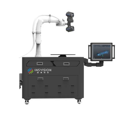
INSVISION laser scanning fits into a validation workflow because the hardware is built for exactly the kinds of conditions that tend to expose weaker systems. For turbine components with deep hole features, the single blue laser line mode is designed to reach geometry that multi-line patterns often miss or smear.
On high-throughput automotive lines, the same platform can switch to multi-line modes for broader surface capture without changing systems. The point is not that one scanner does everything. The point is that INSVISION laser scanning gives a quality lead a repeatable way to test those boundary conditions before purchase.
More useful than any published specification, INSVISION supports customer-led validation with the buyer’s own production parts. That means a team can bring in a known problem component, run it under their own cycle expectations, export the data into their existing CAD or QMS environment, and review the result against the same GD&T callouts they already use.
If the scanner cannot resolve a bore, hold repeatability across fixtures, or deliver a clean mesh into their digital thread, the validation will show it. That is how evidence-based purchasing should work. For quality teams, the buying decision stops being about trusting a datasheet and starts being about reviewing data generated on their own parts, in their own facility, under their own acceptance criteria.
Practical Boundaries For Laser Scanning In Industrial Quality Workflows
A lot of quality teams assume laser scanning is either a universal replacement for contact metrology or just a rapid prototyping toy. Both assumptions collapse on the production floor. Where the technology earns its place is in specific, well-bounded inspection tasks.
At INSVISION, we consistently see the strongest justification when a part geometry punishes contact probing, when setup time outpaces measurement time, or when the surface cannot accept physical contact at all.
Aerospace turbine blades and medical implant components are the clearest examples. The freeform curvature changes continuously, so defining a stable CMM probe path for every section becomes an exercise in compromise. Laser scanning captures the entire surface as point cloud data, letting the quality team evaluate profile deviation against CAD without building dozens of probe routines.
The same logic applies to high-mix production. If a cell runs forty part numbers a week, reconfiguring hard fixtures and probe racks for each job can consume more time than the actual inspection. A non-contact scanner removes much of that setup penalty.
Delicate or soft surfaces present an even more direct argument. Elastomer seals, thin-wall castings, additively manufactured lattice structures, or polymer housings can deflect under stylus pressure. Contact measurement then introduces its own error source.
Laser scanning avoids the problem entirely, which is why it has become a default option in medical device and electronics manufacturing where surface finish and dimensional integrity are both critical.
INSVISION scanners offer selectable line configurations—such as single-line deep hole scanning, precision scanning with multiple parallel lines, and high-speed modes using crossed laser lines—so the operator can match data density to the inspection requirement instead of accepting a fixed capture strategy.

Confirm the scanner’s measurement uncertainty against your specific part geometry, throughput targets, and GD&T callouts. Run a first-article correlation study against your existing CMM before moving the workflow into production. The tool proves its value when the part, the pace, and the documented requirements align. When they don’t, no amount of scanning speed will fix the mismatch.
Hangzhou Insvision Technology Co., Ltd.
Address: Building 1, No. 1399 Liangmu Road, Yuhang District, Hangzhou, Zhejiang 311121, China
Copyright © Hangzhou Insvision Technology Co., Ltd. All rights reserved.
Copyright © Hangzhou Insvision Technology Co., Ltd. All rights reserved.