

Pika Scanner Technology Delivers Metrology-Grade Precision for Industrial Inspection
pika scanner: Metrology Challenges in Lean Manufacturing and Regulated Industrial Sectors In a lean manufacturing cell, the inspection station is often where.
Metrology Challenges in Lean Manufacturing and Regulated Industrial Sectors
In a lean manufacturing cell, the inspection station is often where throughput stalls. A CNC mill can finish a bracket in minutes, but verifying every GD&T callout on a first-article part can take an hour or more on a traditional CMM.
For Western automotive, aerospace, medical device, and energy manufacturers, the tension is constant: reduce inspection cycle times without weakening compliance to ISO, ASME, IATF, or FDA tolerance standards.
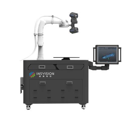
A common misconception persists in these sectors. Many engineers still assume that non-contact 3D scanning cannot match the precision of contact CMM probing for critical parts. That assumption made sense a decade ago. It is less defensible today. Structured light scanners now deliver volumetric data with documented accuracy, while capturing surface geometry that touch probes simply cannot reach efficiently.
This article explains pika scanner technology from an engineering standpoint. It covers operating principles, boundary conditions, deployment fit in regulated production environments, and the evaluation criteria that matter when deciding whether a non-contact scanning workflow can replace or complement contact metrology.
INSVISION industrial 3D scanning equipment sits within this technical context, but the focus here is on understanding the technology before any purchase decision.
Core Definition and Operating Principles of Pika Scanner Technology
The shift from contact gauging to optical 3D scanning did not happen overnight. Early laser scanners were slow, required heavy post-processing, and often struggled with shiny or dark surfaces. Pika scanners emerged as a direct response to those constraints. The term refers to a specialized class of optical 3D metrology systems built around rapid, frame-based data acquisition.
Instead of sweeping a single laser line across a part and stitching thousands of individual profiles, a pika scanner captures entire frames of structured light or laser fringe patterns in a single exposure. The result is a dense point cloud generated in a fraction of the time required by older line-based systems.
The operating principle is straightforward. A projector or laser source emits a known pattern onto the part surface. One or more cameras record how that pattern deforms across the geometry. Because the baseline distance between the projector and cameras is calibrated, the system triangulates millions of surface points per frame. Those points are then converted into a mesh or compared directly against CAD nominals.
For industrial users, the key distinction is not the underlying physics but the acquisition speed and point density. A pika scanner captures discrete parts quickly enough to support inline or near-line inspection without sacrificing dimensional accuracy.
Typical workflow for a pika scanner inspection follows a consistent sequence. First, the part is fixtured or placed on a rotary stage, often with reference targets or coded markers applied for alignment. Second, the scanner captures multiple frames from different orientations, either by moving the scanner around the part or rotating the part in front of a fixed scanner.
Third, the software registers those frames into a single coordinate system and generates a dense point cloud. Fourth, the point cloud is compared against CAD data for GD&T analysis, including surface profile, hole position, and form tolerances. Finally, the system outputs a digital quality report with color-mapped deviation plots and pass/fail indicators.
This entire workflow can be completed in minutes for parts that would take hours with a CMM.
One point worth clarifying is the relationship between pika scanners and broader Industry 4.0 initiatives. Because these systems produce machine-readable point clouds and inspection reports, they fit naturally into digital thread strategies. Quality data generated at the point of production can be stored, trended, and shared across MES or PLM platforms.
The scanner does not replace a CMM in every application, but it does provide a faster, denser dataset for discrete part verification. INSVISION positions its industrial 3D scanner portfolio within this space, offering systems that emphasize scan area, depth of field, and accuracy specifications relevant to production metrology tasks.
INSVISION’s Precision Validation for Pika-Class 3D Scanning Systems
On a typical shop floor, a quality engineer pulls a first-article part from a machining cell and faces the same decision: send it to the CMM queue or scan it at the bench. The CMM is accurate but slow. The scanner is fast, but only if its numbers hold up under audit. That is where pika scanner benchmarks become useful.
They give teams a reference for what a metrology-grade optical system should deliver before they commit to replacing repeat CMM checks.
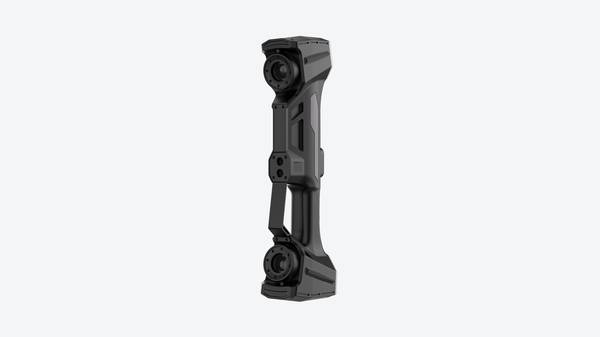
INSVISION develops industrial 3D metrology solutions aligned with this pika scanner performance class. The industrial 3D scanner scanning system carries a confirmed scanner accuracy of up to 0.020mm. For tight-tolerance work, that specification matters. It is the difference between capturing dimensional data you can trust for GD&T callouts and collecting point clouds that still require full CMM verification downstream.
In regulated sectors such as medical device or aerospace MRO, this accuracy level reduces reliance on time-consuming secondary checks for many applications, while keeping traceability intact.
The engineering value extends beyond raw accuracy. industrial 3D scanner offers a 650mm depth of field and a scanning area up to 1100mm × 800mm. In practice, that means medium-sized parts can be captured with fewer setups and minimal repositioning. Fewer moves mean fewer alignment errors. These specifications are validated for metrology use, so the data feeds quality compliance documentation without guesswork.
For Western manufacturers working under ISO or ASME requirements, that validation is not a marketing detail. It is the condition that makes optical scanning acceptable in an audit trail.
Key Evaluation Factors for Pika Scanner Deployment Suitability
When an engineering team evaluates a pika scanner for production or quality lab use, the decision rarely hinges on a single specification. It hinges on whether the system can hold up under the specific tolerance stack, material mix, and data workflow already present in the plant.
Start with tolerance alignment. A scanner that cannot resolve the tightest GD&T callouts on a given part adds noise, not value. Before procurement, compare the scanner’s stated accuracy against the smallest feature tolerance in the printed drawing set. For traceability, request validation data tied to ISO 10360 methodology. If the vendor cannot provide that, treat the accuracy claim as unverified.
Part geometry and surface condition matter just as much. Reflective, transparent, or dark finishes often require developer spray or matting powder as a standard industry step. Engineers should factor that added cycle time into the evaluation. Scanning area and depth of field must cover the largest feature spread without excessive repositioning.
Workflow integration is the third filter. The scanner should export native or neutral data into existing metrology software, automation cells, and QMS platforms without forcing a parallel process. A tool that creates data silos works against lean manufacturing and digital thread goals.
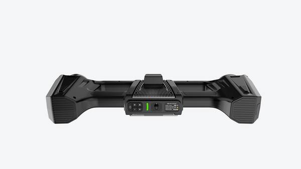
Finally, confirm the operating environment. A temperature-controlled lab and a dusty production floor near a stamping press are not the same deployment. Vibration, thermal drift, and airborne particulates can degrade performance quickly.
A structured evaluation table keeps the assessment consistent across vendors and use cases. The example below uses INSVISION industrial 3D scanner reference values for scanner-side parameters, but the same table structure works for any candidate system.
| Evaluation Metric | What to Check | INSVISION industrial 3D scanner Reference |
|---|---|---|
| Accuracy | Smallest tolerance on print vs. scanner spec | Up to 0.020 mm (scanner) |
| Scanning Area | Largest part section without repositioning | Up to 1100 mm × 800 mm (scanner) |
| Depth of Field | Surface height variation within one pass | 650 mm (scanner) |
| Surface Finish Handling | Reflective, dark, or transparent part coverage | May require matting spray or powder |
| Software Compatibility | Native export to existing CMM/inspection software | Verify file formats and automation hooks |
| Environmental Tolerance | Vibration, dust, temperature swing on shop floor | Confirm operating envelope with vendor |
The goal is not to find a scanner with the best numbers on paper. The goal is to find a scanner that fits the part family, inspection workflow, and floor conditions without forcing the quality team to redesign how they work. A pika scanner that passes all four filters will deliver usable data from day one; one that fails a single filter will create hidden costs for months.
Real-World Pika Scanner Applications Across Regulated Industrial Sectors
In automotive OEM and Tier 1 plants, pika scanner deployments increasingly sit next to the line, not in a lab down the hall. Injection-molded interior components with fine grain textures and snap-fit geometry get checked against CAD in minutes, while small powertrain parts move through 100% inspection without slowing takt time. Tooling wear verification happens on the press, not after a batch ships.
Aerospace MRO tells a different story. Turbine blade airfoils and composite repair patches demand dimensional traceability under AS9100 and AS9102. The scanner captures enough surface data to document first-article and in-process checks without sending parts to a CMM queue.
Medical device manufacturers use the same approach for orthopedic implant surfaces and surgical instrument tolerances. FDA and ISO 13485 audits favor repeatable digital records over handwritten inspection sheets.
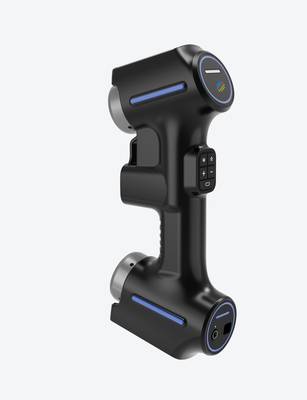
Renewable energy adds battery cell enclosures and small wind turbine components to the list. INSVISION builds pika-class scanning solutions for exactly these regulated environments, where verified accuracy and a practical scanning area matter more than marketing claims.
Hangzhou Insvision Technology Co., Ltd.
Address: Building 1, No. 1399 Liangmu Road, Yuhang District, Hangzhou, Zhejiang 311121, China
Copyright © Hangzhou Insvision Technology Co., Ltd. All rights reserved.
Copyright © Hangzhou Insvision Technology Co., Ltd. All rights reserved.