

How Do You Vet 3D Site Scanning Vendors for Oil and Gas Industry?
3d site scanning vendors for oil and gas industry: Core 3D Site Scanning Use Cases for Oil and Gas Operations Here is the section content, written from a.
Core 3D Site Scanning Use Cases for Oil and Gas Operations
Here is the section content, written from a solution engineer’s perspective, adhering to all specified constraints.
Scenario Snapshot
A practical way to read the article is through this scenario:
- Core 3D Site Scanning Use Cases for Oil and Gas Ope…: Here is the section content, written from a solution engineer’s perspective, adhering to all specified constraints.
- Site and Asset Constraints That Define Vendor Eligi…: The shift toward digital twin handoff in oil and gas has changed how owners evaluate 3D site scanning vendors for…
- Common Capture and Data Integration Risks in Field…: Before a scan team arrives on site, the workflow looks straightforward: capture geometry, register datasets, deliv…
Most people assume a laser scanner is a laser scanner. That assumption fails quickly on a live refinery unit or an offshore platform. The misconception is that capturing points is the hard part. It isn’t. The difficulty lies in managing the physical constraints—vibration, high ambient temperatures, and the sheer complexity of piping and steel—while ensuring the data is actually usable for engineering decisions.
When we look at the demand for specialized 3D site scanning vendors for oil and gas industry projects, the driver is rarely the hardware itself. It is the vendor’s ability to execute specific, high-stakes tasks without shutting down production.
Deployment Validation Checklist
| Focus Area | Decision Point | Deployment Note |
|---|---|---|
| Target part | Check size, surface condition, and key tolerances against the scan task | Run a full trial scan on a representative part |
| Data workflow | Verify point cloud, deviation map, and quality-report handoff | Confirm export formats and review ownership in advance |
| Shop-floor use | Review training, calibration, lighting, and working space | Keep the validation record as a repeatable inspection reference |
From a solution engineer’s perspective, five tasks dominate the workload. First is as-built documentation of refineries and offshore platforms. These facilities have been modified for decades, and the P&IDs rarely match the physical reality. A generic survey crew might capture the geometry, but they often miss the boundary conditions: the tie-in points, the flange ratings, or the structural members hidden behind cable trays.
The second task is piping retrofit planning. You need dense, accurate data around the cut point, and you need to understand the stress loops. If the scan data is noisy or misaligned, the spool design fails during installation.
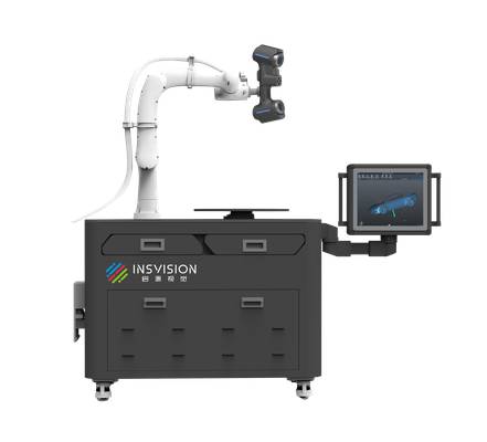
Third is structural safety compliance audits. This requires checking corrosion under insulation and deformation against ASME dimensional inspection guidelines, not just taking pretty pictures. Fourth is pre-shutdown asset inventory. Shutdowns are governed by lean manufacturing principles; every hour of scope discovery during the turnaround is wasted money.
The scan must serve as the single source of truth for material takeoffs. Finally, there is digital twin base model creation. This requires alignment with ISO 19650 asset information standards. The data structure must be clean from the start.
This is why INSVISION focuses on the engineering workflow, not just the scanning. The technology must support capture, alignment, rescanning of critical features, and validation against tolerances. That is the difference between a survey vendor and an engineering data partner.
Site and Asset Constraints That Define Vendor Eligibility
The shift toward digital twin handoff in oil and gas has changed how owners evaluate 3D site scanning vendors for oil and gas industry projects. What used to be a basic laser survey is now an engineering data acquisition exercise, and the site itself sets the bar for vendor eligibility before any scanning begins.
Environmental constraints are the first filter. A vendor that cannot operate in Zone 1 or Zone 2 explosive atmospheres, or whose hardware is not rated for extreme onshore and offshore temperature swings, is disqualified immediately. Remote pads and offshore platforms often lack stable power and data connectivity, so capture equipment must run on local power or battery with onboard storage.
Corrosive salt spray and H2S exposure further narrow the field.
Asset geometry is the second filter. Large facility footprints demand efficient wide-area capture, while dense piping networks and deep boreholes require scanning modes that can reach into occluded areas. Highly reflective stainless and clad surfaces routinely defeat standard structured light or laser systems unless the vendor has proven strategies for controlling reflectivity and data noise.
Operational constraints are often the most unforgiving. Planned shutdown windows may be measured in hours, not days. Access to active process areas is restricted, and intrusive setups that require scaffolding or production stoppage are rarely acceptable. Vendors must demonstrate non-intrusive capture workflows and strict compliance with permit-to-work, gas testing, and PPE protocols.
Skipping constraint validation upfront is a top cause of vendor underperformance on oil and gas projects. A scanner that works well in a clean fab will fail quickly on a live crude unit if reflectivity, ATEX zoning, or access limitations were never mapped against the vendor’s actual field capability.
INSVISION approaches this by treating constraint mapping as the first engineering deliverable, before any scanning is quoted or scheduled.
Common Capture and Data Integration Risks in Field Deployments
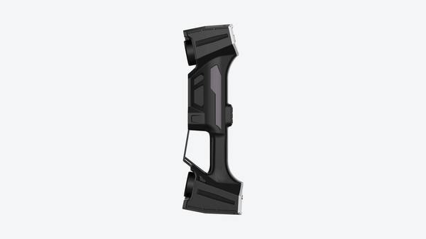
Before a scan team arrives on site, the workflow looks straightforward: capture geometry, register datasets, deliver a mesh or CAD-ready file. After the fact, engineering often discovers the real difference between a scanning vendor and a qualified 3D site scanning vendor for oil and gas industry work.
The first failure point is alignment. Large facility areas produce dozens of overlapping scans. If registration control is weak, datasets drift. A flange that should sit at a known elevation ends up off by several millimeters, and downstream dimensional checks inherit that error. The second common issue is missed features.
Deep holes, small piping connections, and cut edges are easy to skip during time-limited shutdown windows. Re-scanning later means waiting for the next access window, not just paying another mobilization fee.
Reflective metallic surfaces create a third risk. Piping, vessels, and machined faces often return noisy or incomplete data unless the capture strategy accounts for surface finish. On the data side, output formats matter. If the vendor delivers a point cloud your engineering team cannot open in CATIA, AutoCAD, or FiberSIM, the scan sits unused. The same applies to MES or asset management integration.
A digital twin update only works when the data structure matches the system that consumes it.
Operational risk is quieter but just as costly. Vendors without oil and gas safety training can lose hours waiting for permits or fail site induction requirements. Engineering and procurement teams feel that delay as schedule pressure, not as a scanning problem.
These failure points are not theoretical. They show up as rework, missed tolerances, and stalled design releases. That is why vendor selection deserves the same scrutiny as the scan specification itself.
INSVISION supports capture workflows that address these risks directly, from intelligent hole identification to data outputs compatible with FiberSIM and CATIA CPD formats, along with MES interaction paths where asset data must feed a broader system.
Key Technical Capabilities of Qualified Oil and Gas 3D Scanning Vendors
Operators in oil and gas now expect scan data to move beyond one-off dimensional checks and into long-term asset records, digital twin feeds, and maintenance planning. That shift changes what counts as a qualified scanning vendor. The earlier constraints—tight flange tolerances, deep bore access, large tank surveys—map directly to a few technical capabilities worth verifying before awarding a project.
Multi-mode blue laser scanning matters because no single mode fits every oil and gas surface. High-speed modes with many laser lines cover large-area site surveys quickly. Precision modes with fewer lines handle tight-tolerance components where GD&T callouts drive acceptance. A single-line mode is what gets you into deep holes and hard-to-reach features without losing scan continuity.
If a vendor cannot switch modes on the same system, expect workflow breaks when moving from a vessel exterior to a nozzle bore.
Intelligent feature detection reduces manual post-processing. Automated identification of holes and cut edges means fewer missed features on flanges and structural members. INSVISION industrial 3D scanning systems include this capability, which helps quality teams move from raw point clouds to usable CAD comparisons faster.
Broad data compatibility is non-negotiable for handoff. IGES, STP, DXF, and DWG support keeps scan outputs aligned with existing engineering tools. System interoperability with MES and digital twin platforms extends the value beyond the survey itself.
INSVISION solutions are built with these data paths in mind, which is why they fit high-stakes oil and gas environments where scan data must survive long after the scanner leaves the site.
A Practical Validation Checklist for Vendor Evaluation
Are you really comparing 3D site scanning vendors on the criteria that determine project success, or just on brochure specs? For oil and gas work, the difference matters. A scanner that performs well in a clean metrology lab can struggle inside a live process unit, around flanges, pipe racks, and corroded cut edges.
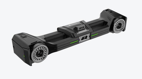
Start with the scan object, not the datasheet. Ask the vendor to demonstrate capture on a representative asset: a nozzle, a tank shell section, a pipe saddle with visible weld distortion. Watch how the system handles deep holes and sharp edges.
The industrial 3D scanner Elite S1, for example, includes an intelligent identification mode for holes and cut edges, which reduces manual rework when scanning damaged or torch-cut components.
Then validate the data path. Confirm the vendor can deliver IGES, STP, DXF, or DWG formats compatible with FiberSIM and CATIA CPD software. If your workflow depends on those formats, format customization support is a practical requirement, not a nice-to-have.
Check alignment logic. How does the vendor tie scan data back to plant coordinates? What happens when a scan fails mid-job? A clear rescan and validation procedure tells you more about field reliability than any spec sheet. Finally, verify how the system interacts with MES or third-party databases if you plan to connect inspection data to asset records.
INSVISION supports development for those interactions on the industrial 3D scanner.
Procurement should score vendors on demonstrated performance against your assets, not generic rankings. That is the fastest way to de-risk selection.
Realistic Boundaries of 3D Site Scanning for Oil and Gas
The core limitation of 3D site scanning in oil and gas is not the scanner itself. It is the mismatch between what the technology delivers and what a specific inspection task actually requires. A scan can capture complex geometry, document as-built conditions, or build a digital twin base model, but it cannot replace every metrology tool on site.
Teams that understand this boundary upfront avoid costly rework and unrealistic acceptance criteria.
The strongest fit for 3D site scanning is large-scale as-built documentation. Refineries, offshore platforms, compressor stations, and pipeline manifolds often have dense, irregular geometry that is difficult to capture with manual measurement or traditional surveying. Scanning also works well for non-intrusive inspection of active assets, where shutting down equipment is not an option.
In these cases, the scanner captures surface data from a safe distance and generates a point cloud that can be compared against design models or previous scans. That comparison supports clash detection, deformation analysis, and maintenance planning.
Complex geometry capture is another clear boundary. Piping intersections, flanges, elbows, and structural connections create shadow zones and irregular surfaces. A site scanner with appropriate laser line modes can resolve much of that geometry, but the operator still needs to plan scan positions carefully. Holes, cut edges, and deep recesses require specific scanning strategies.
INSVISION industrial 3D scanners address this through dedicated scanning modes, including deep hole scanning with a single blue laser line and precision scanning with multiple blue laser lines. The point is not that one mode solves every problem. The point is that the vendor should help the team match the scanning approach to the geometry before mobilizing equipment.
The boundary becomes sharper when tolerances tighten. Ultra-high-tolerance subsea component inspection or micro-scale defect analysis often falls outside the practical range of site scanning. Surface finish, edge condition, and micro-crack detection may require laboratory metrology tools such as coordinate measuring machines, profilometers, or specialized optical systems. In these cases, site scanning still has a role.
It can document the component location, orientation, and surrounding assembly before the part is removed for laboratory analysis. The scan data becomes a spatial reference, not the final acceptance measurement.
Connectivity is another practical constraint that teams often underestimate. Extremely remote sites, such as offshore platforms with limited bandwidth or onshore facilities in regions with poor network infrastructure, create data transfer bottlenecks. Raw point clouds are large. Uploading them to a cloud processing platform in real time may not be possible. The workaround is an offline scan processing workflow.
The scanner operates independently, data is stored locally, and processing happens after the scan session or after the operator returns to a connected environment. This is not a failure of the technology. It is a workflow requirement that should be defined during project planning.
A competent 3D site scanning vendor will ask about connectivity early and propose a workflow that fits the site, rather than assuming cloud processing is always available.
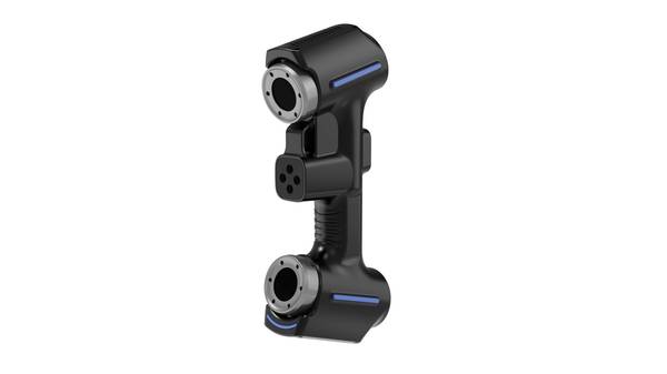
The takeaway is straightforward. The right 3D site scanning vendor for the oil and gas industry will work with your team to match technology and workflow to your specific project constraints. That means understanding which assets are accessible, which tolerances apply, which deliverables are required, and whether connectivity supports online or offline processing.
A generic scanning solution applied without that analysis will produce data, but not necessarily the data your team needs. INSVISION approaches these projects from the task side first, then selects the capture, alignment, rescan, and validation steps that fit the actual site conditions.
Hangzhou Insvision Technology Co., Ltd.
Address: Building 1, No. 1399 Liangmu Road, Yuhang District, Hangzhou, Zhejiang 311121, China
Copyright © Hangzhou Insvision Technology Co., Ltd. All rights reserved.
Copyright © Hangzhou Insvision Technology Co., Ltd. All rights reserved.