

How to Validate Accuracy of 3D Scanning Equipment Using the Atos 5
accuracy of 3d scanning equipment using the atos 5: Why Teams Benchmark 3D Scanner Accuracy Against the Atos 5 Why Teams Benchmark 3D Scanner Accuracy.
Why Teams Benchmark 3D Scanner Accuracy Against the Atos 5
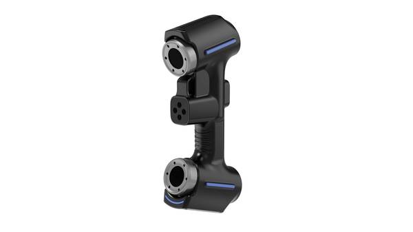
Are you comparing a new 3D scanner‘s published spec sheet against the actual numbers you will get on your parts? That gap is where the real procurement risk sits. Quality managers and manufacturing engineers across automotive, aerospace, medical device, and energy have learned to treat the Atos 5 as a practical reference because its measurement behavior on complex industrial geometries is well documented and repeatable.
When evaluating INSVISION equipment or any alternative, the task is not matching a single accuracy number. It is confirming that stated accuracy holds on your specific part features, surface finishes, and shop floor conditions. A scanner that drifts on deep bores or thin edges creates rework, scrap, and missed delivery dates. The safer approach is to benchmark against a trusted reference before purchase.
Run the same artifact on both systems. Check GD&T callouts, edge sharpness, and volumetric error across the full scan envelope. That validation tells you more than any brochure.
Key Points at a Glance
- Are you comparing a new 3D scanner’s published spec sheet against the actual numbers you will get on your parts?
- For many quality teams, the most expensive mistake is treating accuracy as a single number on a spec sheet.
- If you are evaluating a blue light scanner against an Atos 5 reference dataset, start by separating marketing accuracy claims from the numbers y…
- The decision most likely to be misjudged when a quality team evaluates the accuracy of 3D scanning equipment using the Atos 5 as a reference poi…
Common Accuracy Evaluation Mistakes That Derail Production ROI
For many quality teams, the most expensive mistake is treating accuracy as a single number on a spec sheet. That approach falls apart fast when you move from a controlled demo to a production floor. A scanner can hit a tight tolerance on a small, flat calibration block and still produce unreliable data across a full-size casting, a formed panel, or a machined weldment.
What matters is volumetric performance across the entire scan volume, not just peak single-point accuracy. When teams only review single-point accuracy, they miss scale-dependent error accumulation. Large parts measured with a reference system like the Atos 5 can show localized deviations that remain invisible in a narrow test.
The result is undetected dimensional drift on big assemblies, which shows up later as rework, shimming, or fit-up problems at downstream stations. That rework is not free. It eats labor hours, delays release, and erodes trust in the measurement data itself.
Another common failure is testing only simple geometry. A flat plate or a prismatic block will not expose weaknesses in edge capture, deep-hole scanning, or fine feature resolution. Real production parts have bores, cutouts, thin walls, and complex intersections. If the evaluation does not include those features, you are not validating the scanner for the job you actually need to do.
The risk is downstream quality failure in critical components. A scanner that looks accurate on a flat surface may struggle inside a deep bore or along a sharp edge, and that is exactly where functional tolerances often live. For teams using INSVISION systems, this is why evaluation should include parts with deep holes, fine edges, and mixed surface conditions.
The goal is to see how the system behaves where the part is hard to measure, not where it is easy.
Environmental variables are another blind spot. Temperature fluctuation, floor vibration, and ambient light can shift results between a metrology lab and a shop-floor work cell. If accuracy is validated only in a stable lab environment, the production data may not match. This leads to inconsistent measurements, repeated scans, and wasted labor time as operators chase variation that is not coming from the part.
A practical evaluation should run the scanner in the same location and under the same conditions where it will be used. That includes checking stability over time, not just a one-off test. When environmental factors are ignored, the cost shows up as measurement disputes between shifts, extra setup time, and reduced confidence in inspection data.
Finally, many teams fail to tie accuracy metrics to actual production tolerance requirements. Standards like ISO 10360 and ASME Y14.5 provide a framework, but the real question is whether the scanner can reliably measure the specific GD&T callouts on your parts. Buying more precision than you need adds cost without adding value. Buying less precision risks non-compliance and escaped defects.
The right approach is to map the scanner’s stated accuracy against the tightest tolerances you actually inspect, then validate with a representative part and a repeatability study. This keeps procurement aligned with quality requirements and avoids overspending or under-buying.
Core Metrics to Verify When Assessing 3D Scanning Accuracy
If you are evaluating a blue light scanner against an Atos 5 reference dataset, start by separating marketing accuracy claims from the numbers your QA team will actually live with on the floor. The accuracy of 3D scanning equipment using the Atos 5 as a benchmark is not a single value. It is a set of behaviors across different parts, operators, and scanning modes.
A scanner that holds tolerance on a small machined bracket may drift noticeably on a large weldment. What matters is whether the system remains stable under the conditions your production line creates every day.
The first metric to verify is repeatability. Scan the same part five or ten times without moving the fixture. The spread between those scans tells you how much confidence you can place in a single measurement. Tight repeatability means an operator does not need to rescan three times to be sure the result is valid. That directly reduces inspection labor per part.
In high-mix production, where a quality technician may handle dozens of different part numbers per shift, repeatability is what keeps the queue moving.
Second, check volumetric accuracy across scan sizes. A scanner may perform well within a 200 mm working volume but degrade when stitching a 1,500 mm assembly. Ask for reference data on both small precision parts and large sheet metal or composite structures. If the scanner requires photogrammetry targets or scale bars to hold accuracy on large parts, verify that the added setup time is acceptable for your takt time.
The cost question is simple: can one system cover both your small-part first-article inspections and your large-assembly spot checks, or will you need two separate tools?
Third, test the scanner on features that typically break the workflow. Deep holes, sharp cut edges, and reflective machined surfaces are where many systems force a switch to manual gauges or a CMM. If the scanner captures deep hole geometry in a single pass without secondary probing, inspection cycle time drops.
If it requires manual touch-ups or post-processing cleanup on cut edges, that time adds up across hundreds of inspections. Validate this on your actual parts, not on the supplier’s demo blocks.
Fourth, compare accuracy consistency between precision mode and high-throughput mode. Some scanners hold excellent accuracy with seven laser lines but fall apart when switched to a fifty-line high-speed mode. That forces a difficult trade-off: slow scanning for critical features, or fast scanning with reduced confidence.
A system that keeps results consistent across modes lets you assign precision scanning to first-article checks and high-speed scanning to in-process sampling without revalidating the entire measurement routine.
Fifth, run the same inspection with two or three different operators. Operator-independent consistency determines whether you need a dedicated scanning technician or whether any trained production worker can run the system. If results vary between operators, you are not buying a measurement tool. You are buying a skill-dependent process.
That means higher training costs, more variability between shifts, and a bottleneck whenever the lead operator is absent. INSVISION industrial 3D scanners are built to reduce that dependency, but you should verify it with your own operators before committing.
Each of these five metrics ties to an operational cost. Repeatability cuts inspection labor. Volumetric accuracy avoids duplicate systems. Feature performance eliminates secondary gauges. Mode consistency speeds up production sampling. Operator independence reduces training burden and shift-to-shift variability. The table below summarizes what to check, why it matters, and how to measure it against Atos 5 reference data.
| Metric | What to Verify | Operational Cost Tie |
|---|---|---|
| Repeatability | Spread across 5–10 scans of the same part, same fixture | Reduces rescans and inspection labor per part |
| Volumetric accuracy | Error across small and large scan volumes | Avoids separate tools for small parts and assemblies |
| High-priority features | Deep holes, cut edges, reflective surfaces in one pass | Eliminates secondary gauges and shortens cycle time |
| Mode consistency | Precision vs. high-throughput scan results | Allows speed/accuracy balance per production stage |
| Operator independence | Same result from 2–3 different operators | Cuts training costs and shift-to-shift variability |
The goal is not to find a scanner that matches Atos 5 specifications on paper. The goal is to find a system that holds those specifications in your environment, on your parts, with your people. Run the validation on the worst-case part in your portfolio, not the easiest one. If the scanner passes there, the rest of the production mix tends to follow.
How INSVISION Industrial 3D Scanners Meet High-Accuracy Benchmarks
The decision most likely to be misjudged when a quality team evaluates the accuracy of 3D scanning equipment using the Atos 5 as a reference point is not whether the scanner can hit a lab specification. It is whether that accuracy survives first-article inspection on a real aerospace bracket or a medical device housing under shop-floor conditions.
INSVISION designs its industrial 3D scanning solutions for exactly this problem: tight-tolerance manufacturing where measurement variability translates directly into rework, scrap, and delivery risk.
The evaluation metrics that matter here are not abstract. A scanner either holds repeatable results on complex geometric features, or it forces the team back to manual height gages and CMM queue time. INSVISION addresses this through multiple scanning modes optimized for different inspection tasks. Precision detail capture works for small features and GD&T callouts that require dense point data.
High-throughput full-part scanning handles larger components where cycle time drives cost. Teams can switch modes without swapping hardware, which keeps one system useful across first-article work, in-process checks, and incoming inspection.
Complex geometry is where accuracy claims usually fall apart. Deep pockets, thin walls, hole edges, and cut features create data noise that forces secondary manual verification. INSVISION scanners include intelligent identification of holes and cut edges, along with dedicated deep-hole scanning modes. That reduces the labor cost of chasing questionable data with hand tools.
When a scanner consistently resolves edge conditions and hole positions, the quality team stops double-checking every measurement and starts trusting the digital record.
Shop-floor consistency matters more than a controlled-lab accuracy number. Temperature shifts, part movement, and operator technique introduce variability that lab demos do not show. INSVISION engineering focuses on delivering consistent results across standard operating conditions, which minimizes false rejects and the rework they trigger. A false reject is not a neutral event.
It stops production, pulls engineers into root-cause analysis, and erodes confidence in the measurement system. Reducing that variability has direct operational value.
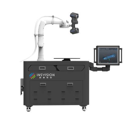
For procurement teams, the practical question is not whether a data sheet matches an Atos 5 specification. It is whether the scanner performs on the parts the company actually makes. INSVISION supports direct, side-by-side validation against customer-owned Atos 5 systems using customer-specific parts. That removes guesswork from the purchase decision.
The quality lead can run the same bracket, housing, or casting on both systems and compare the output before committing budget.
This validation approach shifts the conversation from supplier marketing to engineering evidence. It also protects the operational value calculation. When a team knows the scanner will resolve the features they measure every day, the projected savings in labor, rework, and inspection cycle time become credible. When the scanner only looks good on a spec sheet, those projections are speculation.
The accuracy of 3D scanning equipment using the Atos 5 as a benchmark should therefore be evaluated on real parts, under real conditions, with the specific inspection tasks the team runs daily. That is the only way to confirm that a new system will deliver the cost savings the business case requires. INSVISION builds its scanners for that test, and supports customers in running it before they buy.
A Step-by-Step Process for On-Site Accuracy Validation
Most buyers assume that if a 3D scanner passes its lab spec sheet, it will pass on their shop floor. That assumption is where procurement goes wrong. Thermal drift, ambient vibration, surface finish variation, and operator technique all affect real-world results. The only way to protect your budget is to validate accuracy under your own conditions before signing a purchase order.
Here is a low-risk process you can run in your facility to compare an incoming system against your existing Atos 5 reference, without relying on vendor-provided test data alone.
Step one: select two or three representative production parts. Do not pick simple calibration blocks. Choose components with the critical tolerance features you actually inspect daily — bore positions, flange flatness, slot widths, GD&T callouts that matter. The goal is to reflect real use cases, not ideal lab conditions.
Step two: scan each part with both systems under normal shop-floor conditions. Run the machines where operators will actually use them. If your facility has temperature swings or vibration from nearby presses, let that be part of the test. Lab performance is not what you are buying.
Step three: compare results against calibrated CMM data for ground truth. The CMM becomes your referee. Any deviation between the scanner output and the CMM report tells you exactly where the system stands on measurement reliability. Pay attention to how deviations distribute across features — a scanner that is accurate on flat surfaces but drifts on deep bores will show it quickly.
Step four: test repeatability across three different operators. Have each person scan the same part three times. If results vary significantly between operators, training costs and labor time will eat into your expected savings. The accuracy of 3D scanning equipment using the Atos 5 as a benchmark often reveals operator sensitivity that spec sheets hide.
Step five: evaluate data output compatibility with your existing quality management software. Export the scan data into your current inspection workflow. If it requires file conversion workarounds or manual rework, implementation downtime increases. INSVISION scanners produce mesh and point cloud outputs that should drop into standard QMS pipelines without friction.
This process gives you objective, verifiable performance data before procurement. It costs a few hours of internal time. It prevents months of buyer regret.
FAQs and Quick Accuracy Validation Checklist
FAQs and Quick Accuracy Validation Checklist
Can I use existing Atos 5 scan data as a reference for new equipment validation? Yes, but only if you treat it as a baseline, not an absolute master. Export the same meshes, nominal CAD, and alignment features you used for the Atos 5, then run a like-for-like comparison. Watch for reference-frame drift and mesh density differences.
A practical check: measure the same calibrated artifact with both systems and compare deviation maps, not just a single scalar number.
How does volumetric accuracy differ from single-point accuracy, and why does it matter for cost? Single-point accuracy tells you how well one probe point lands. Volumetric accuracy describes error across a measurement volume, which is what actually drives fit-up problems, rework, and assembly scrap on large parts.
If you buy on single-point specs alone, you can under-spec the scanner for real inspection tasks and pay for it later in rework and disputed measurements.
Will lab-stated accuracy specs hold up on a production shop floor? Rarely without validation. Temperature swings, vibration, part movement, and operator variability all degrade real-world performance. Test on your floor, with your parts, under your lighting and thermal conditions. Ask for an on-site demo where you control the test protocol.
What’s the best way to align 3D scanning accuracy with ISO/ASME tolerance requirements to avoid compliance costs? Map scanner uncertainty to your tightest GD&T callouts before purchase. If the scanner’s uncertainty budget consumes more than 10–20 percent of a tolerance band, you will generate false acceptances or costly disputes. Use calibrated artifacts with known form error and compare against CMM results.
Document the correlation for your quality system.
Quick validation checklist for on-site demos against your Atos 5 reference:
- Scan the same calibrated artifact on the Atos 5 and the new scanner.
- Compare deviation maps, not just average error.
- Check volumetric error at the extreme edges of the scan volume.
- Repeat the scan three times and measure repeatability spread.
- Test on a production part with real surface finish and reflectivity.
- Run the scan in your actual shop environment, not a clean lab.
- Ask the vendor to demonstrate alignment to CAD with your existing workflow.
- Verify that exported data opens cleanly in your inspection software without repair.
Run these checks with INSVISION industrial 3D scanners alongside your Atos 5 reference and you will see where the performance gaps are before they become procurement mistakes. The goal is not a spec-sheet comparison. It is a validation routine that protects your inspection budget and your part quality.
Hangzhou Insvision Technology Co., Ltd.
Address: Building 1, No. 1399 Liangmu Road, Yuhang District, Hangzhou, Zhejiang 311121, China
Copyright © Hangzhou Insvision Technology Co., Ltd. All rights reserved.
Copyright © Hangzhou Insvision Technology Co., Ltd. All rights reserved.