

3D Scanning Machine Technology for Industrial Metrology: Principles, Workflows, and Shop-Floor Validation
The gap between what a coordinate measuring machine (CMM) can deliver and what a modern production line actually needs has never been wider.
It explains what a 3D scanning machine actually does, how it fits into inspection and reverse engineering workflows, where the technology delivers genuine value, where it should not be used, and what teams must validate before the first scan on the shop floor.
What a 3D Scanning Machine Actually Does
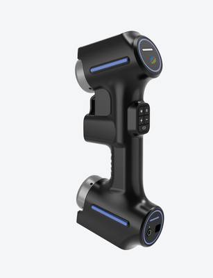
At its core, a 3D scanning machine is a non-contact digitizer that projects structured light or laser lines onto a part and captures the reflected pattern with onboard cameras. The system triangulates millions of points per second, building a dense point cloud that maps the as-built surface. That point cloud is then converted into a polygon mesh — a digital twin of the physical part.
Unlike a touch probe, which records one coordinate at a time, a handheld 3D scanner generates a continuous surface representation. The operator moves the scanner around the part as if spray-painting it with light. On an INSVISION AlphaScan, a live mesh preview builds instantly on the screen, so the operator sees exactly which areas still need coverage.
This eliminates the guesswork about whether enough data has been captured before the part leaves the fixture.
The raw output of a 3D scanning machine is a set of measured coordinates, typically in the millions. The engineering value emerges when that mesh is aligned to a nominal CAD model and compared point-by-point. The software produces a full-field deviation map, color-coding the surface according to user-defined tolerances.
Instead of interpreting a few dozen CMM points, the team sees a continuous picture of form error, profile deviation, and localized distortion.
Key Technical Elements
Any discussion of 3D scanning machine performance should start with the conditions that govern data quality, not just a line item in a specification sheet.
Point density and resolution. The scanner’s camera resolution and projection pattern determine how finely it samples the surface. For feature-rich castings with tight radii, higher point density prevents missing small geometry transitions. For large, gently curved panels, moderate density is enough.
Volumetric accuracy and repeatability. A metrology-grade 3D scanning machine is typically validated against certified reference artifacts. The key question is: if the same part is scanned multiple times — by different operators, across shifts — how tightly do the point clouds align?
Verification with a calibrated sphere or gauge block, both immediately after warm-up and an hour into operation, reveals whether the system holds its stated repeatability in the actual environment.
Mesh fidelity versus inspection-ready data. A dense mesh looks impressive, but its value for metrology depends on how faithfully it represents the part surface. Smoothing algorithms that fill holes or soften sharp edges can hide real deviations. Industrial workflows demand raw, unfiltered mesh data that can be compared directly to CAD without intermediate artistic edits.
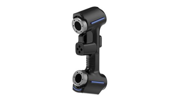
Software integration. The scanner is only half the system. The software that handles alignment, GD&T extraction, and reporting determines whether the machine becomes a process control tool or a disconnected measurement gadget. A tight capture-to-report workflow — point cloud, mesh, CAD alignment, deviation map, annotated report — keeps the entire inspection traceable.
| Parameter | What to Evaluate |
|---|---|
| Point density / resolution | Minimum feature size the scanner can resolve on representative parts |
| Volumetric accuracy | Deviation against a traceable reference artifact under shop-floor conditions |
| Repeatability | Point cloud spread across multiple scans, operators, and thermal states |
| Software capability | GD&T annotation, MBD alignment, automated report generation, and export formats |
How 3D Scanning Differs from Traditional CMM and Other Metrology Tools
A bridge CMM with a touch probe remains the default choice when a drawing calls for a few dozen linear dimensions on prismatic parts with tight, two-micron tolerances. The probe contacts the surface at discrete points, and the measurement is traceable to the machine’s scale.
A 3D scanning machine offers a fundamentally different data set. It captures the entire surface, not a sampling of points.
- Profile and form tolerances where the boundary of the entire surface matters.
- Parts with complex, organic geometry that would require thousands of probe points to characterize.
- First-article inspection where the goal is to understand all deviations, not just a pre-selected list.
The trade-off is that a 3D scanning machine typically cannot match the point-to-point repeatability of a high-end CMM in a temperature-controlled lab. However, on the shop floor, where thermal drift, vibration, and part handling affect any measurement, the speed and coverage of scanning often provide a more complete picture of the true part condition than a CMM brought to the floor.
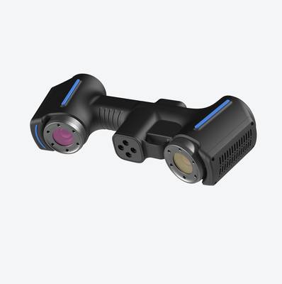
Structured light scanners, laser line scanners, and photogrammetry systems each occupy different niches. Handheld laser scanners offer flexibility for large castings and assemblies. Desktop structured light systems excel at small, detailed parts in a controlled setting. The INSVISION AlphaScan, a handheld laser scanner, is designed for shop-floor agility — large parts, in-situ inspections, and assemblies that cannot be moved.
Where It Excels and Where It Doesn’t
Suitable scenarios
- First-article inspection of castings, injection-molded parts, and 3D-printed components where freeform surfaces dominate.
- In-line dimensional checks on large fabrications, weldments, and composite layups that are impractical to fixture on a CMM.
- Maintenance, repair, and overhaul (MRO) of legacy parts with no CAD data — scanning captures the as-worn geometry for reverse engineering.
- Assembly verification, such as checking flushness and gap conditions across body panels or airframe skins.
Less suitable scenarios
- Parts with extremely deep, narrow bores that the scanner’s line of sight cannot reach.
- Shiny, mirror-like, or transparent surfaces without proper preparation (scanning spray or powder is often required, and the coating thickness must be accounted for in the measurement uncertainty).
- Applications demanding sub-five-micron point-to-point uncertainty under unconstrained shop-floor conditions.
- Very small features that fall below the scanner’s minimum resolvable feature size.
The boundary condition is not just the part, but the environment. A 3D scanning machine’s accuracy is specified under reference conditions. On the shop floor, stray vibration, ambient light changes between shifts, and temperature swings of more than a few degrees can introduce noise or drift.
The fixture setup matters just as much: a part that shifts slightly under its own weight will produce a mesh that looks accurate but drifts out of tolerance on critical GD&T callouts.
Shop-Floor Validation Before Deployment
More manufacturers are moving 3D scanning out of the quality lab and directly onto the production line, treating it as a process control tool rather than a one-off measurement exercise. That shift requires a disciplined validation routine.
Before the first production scan, the team should
Hangzhou Insvision Technology Co., Ltd.
Address: Building 1, No. 1399 Liangmu Road, Yuhang District, Hangzhou, Zhejiang 311121, China
Copyright © Hangzhou Insvision Technology Co., Ltd. All rights reserved.
Copyright © Hangzhou Insvision Technology Co., Ltd. All rights reserved.