

3D Scanner to STL Workflow Validation for Reliable Factory Integration
In practice, the handoff between scanning and actionable STL data is where many implementations stall. One overlooked gap is mesh specification alignment.
Common Deployment Risks for 3D Scanner to STL Industrial Workflows
When a production quality team integrates a 3D scanner to generate STL files for first-article inspection or tooling validation, the workflow on paper looks straightforward: scan the part, mesh the point cloud, export an STL, and compare it against the CAD nominal. In practice, the handoff between scanning and actionable STL data is where many implementations stall. One overlooked gap is mesh specification alignment.
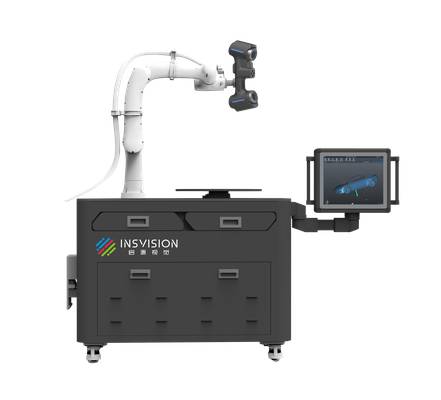
An STL with too-coarse tessellation can mask subtle surface deviations that matter for GD&T callouts on sealing surfaces or mating features. Conversely, an overly dense mesh bogs down downstream inspection software and creates long processing queues that conflict with line-side takt time expectations.
Practical Workflow
- Common Deployment Risks for 3D Scanner to STL Industrial… — When a production quality team integrates a 3D scanner to generate STL files for first-article inspection or tooling validation…
- Pre-Deployment Sample Validation: Matching STL Outputs to… — Before the AlphaAutoScan-400 ships, INSVISION runs a structured pre-deployment validation that eliminates the usual scramble to m…
- On-Site Implementation and STL Data Flow Integration — Integrating the AlphaAutoScan-400 into a live production line succeeds not by ripping out existing processes, but by threading th…
- Role-Specific Training and Post-Deployment Performance Re… — A 3D scanner only delivers value when the people using it produce consistent, auditable STL output that fits into an existing qua…
Bottlenecks often accumulate between scan cycles and STL export because teams underestimate the time needed for mesh cleanup, alignment, and format validation. A scanner that captures data quickly means little if operators spend an extra 20 minutes per part manually trimming noise and healing mesh defects before the STL is usable.
Deployment Validation Checklist
| Focus Area | Decision Point | Deployment Note |
|---|---|---|
| Target part | Check size, surface condition, and key tolerances against the scan task | Run a full trial scan on a representative part |
| Data workflow | Verify point cloud, deviation map, and quality-report handoff | Confirm export formats and review ownership in advance |
| Shop-floor use | Review training, calibration, lighting, and working space | Keep the validation record as a repeatable inspection reference |
In high-mix production environments, this unplanned touch time directly undermines lean process efficiency and can delay batch release.
Site constraints are another frequent blind spot. A scanner that performs well in a metrology lab may be unsuitable for an ISO 7 cleanroom where particle shedding from cables or housing materials becomes a contamination risk. Or a system that requires a fixed enclosure might not fit beside a moving conveyor where the inspection window is only 18 seconds.
When procurement evaluates a 3D scanner to STL solution without mapping these physical and protocol constraints, the result is a tool that sits idle—or worse, disrupts production flow during rollout.
INSVISION addresses these deployment risks by treating the STL output as a production deliverable, not an afterthought. The AlphaAutoScan-400, for example, integrates automated mesh generation with configurable export presets that match the resolution and format requirements of common QA software platforms, reducing the manual intervention that creates bottlenecks.
Pre-Deployment Sample Validation: Matching STL Outputs to Operational Needs
Before the AlphaAutoScan-400 ships, INSVISION runs a structured pre-deployment validation that eliminates the usual scramble to make STL outputs work with existing quality systems. The process starts when a tier-1 automotive supplier sends in a set of stamped metal parts—say, a door inner panel with deep draws and tight springback—along with the CAD nominal and a list of critical-to-quality features. The engineering team doesn’t just scan and send files back. They sit down with the supplier’s quality and metrology leads to lock in three parameters that define the entire 3D scanner to STL pipeline: mesh density requirements for GD&T extraction, the exact binary or ASCII STL format their QMS and reverse-engineering software expects, and the dimensional tolerance alignment method that ties the scan data to the part’s datum reference frame.
Test parts go through the full automated cycle: robotic loading, structured-light capture, and background processing that generates the STL mesh. The team then validates that those STL files open natively in the supplier’s inspection software—no translation errors, no missing surface data where the mesh needed to be watertight, no coordinate system mismatches that would throw off a profile tolerance check.
If the stamped part has deep ribs or tight radii, the validation deliberately probes where data continuity might break. The output isn’t a generic “pass.” It’s a documented sample report that confirms the STL behaves exactly as the downstream workflow requires, and it sets a measurable benchmark for what the system will deliver once installed on the plant floor.
Practical limits get surfaced here, not after commissioning. Complex geometry with high aspect ratio pockets or near-vertical walls can produce sparse mesh regions if scan angles aren’t optimized; the validation flags those and defines the scanning strategy adjustments needed.
Delivery rhythm—how many parts per hour can be scanned and meshed without compromising STL integrity—is tested against the supplier’s expected takt, so there are no surprises about cycle time versus quality. This step makes the 3D scanner to STL process predictable. The equipment leaves the facility with a repeatable recipe, not a hope that it will work on site.
On-Site Implementation and STL Data Flow Integration
Integrating the AlphaAutoScan-400 into a live production line succeeds not by ripping out existing processes, but by threading the 3D scanner to STL workflow directly into the lean manufacturing structure already in place. The on-site team first maps the physical station to the natural flow of parts—often post-machining or at the CMM queue—so an operator loads a component and triggers a scan without walking away from the line.
As the scan completes, network configuration does the heavy lifting: STL files are automatically routed to pre-assigned team folders, a shared PolyWorks workspace, or a cloud repository tied to SAP QM, depending on the downstream task. SolidWorks users retrieve the same STL without re-exporting, eliminating the manual shuffle that typically introduces version errors.
Configurable scan recipes hard-code the part-specific settings—resolution, extraction boundaries, GD&T callouts—so every STL reflects the pre-approved inspection plan.
Role-Specific Training and Post-Deployment Performance Reviews
A 3D scanner only delivers value when the people using it produce consistent, auditable STL output that fits into an existing quality workflow. INSVISION builds that capability into the deployment from day one with role-specific training and a structured 30-day performance review. The training is tiered to match how cross-functional teams actually touch the 3D scanner to STL workflow.
Quality technicians learn to initiate scan cycles, verify STL file integrity against the master CAD, and flag any mesh anomalies before the data moves downstream. Process engineers get hands-on with adjusting scan recipes for new part numbers — tweaking exposure, resolution, and alignment strategies so the scanner-to-STL pipeline stays repeatable when part geometry changes.
Maintenance staff receive instruction on basic system upkeep: cleaning optics, checking calibration artifacts, and performing the daily verification routines that keep the scanner in a validated state. This role-based approach means no single person needs to be an expert on everything, and shift-to-shift handoffs stay clean.
The 30-day post-deployment review then locks in that consistency. The INSVISION team works alongside on-site staff to confirm the entire workflow meets pre-agreed operational criteria — things like STL file accuracy against a known artifact, scan cycle time under real production pacing
Applying This Validation Framework Across Industrial Use Cases
Is your operation generating enough STL data to justify a purpose-built scanning cell? The structured 3D scanner to STL approach delivers its strongest return when scan outputs must flow directly into downstream CAM, FEA, or dimensional inspection software without manual alignment and meshing. Four industrial scenarios consistently benefit from this pipeline.
Aerospace MRO teams use it for reverse engineering high-value components where the STL mesh becomes the digital twin for CNC rework. Medical device groups apply it to implant dimensional inspection, verifying GD&T callouts against a CAD model and archiving the resulting STL as a controlled quality record.
In the energy sector, turbine component tooling verification relies on batch-generated STL files to check forging die wear against the original design intent.
Hangzhou Insvision Technology Co., Ltd.
Address: Building 1, No. 1399 Liangmu Road, Yuhang District, Hangzhou, Zhejiang 311121, China
Copyright © Hangzhou Insvision Technology Co., Ltd. All rights reserved.
Copyright © Hangzhou Insvision Technology Co., Ltd. All rights reserved.