

3D Scanning Deep Cavities – What Spec Sheets Dont Tell You
A scanner might deliver 0.020 mm volumetric accuracy on a calibration artifact, yet fail completely inside a deep cavity.
The Spec Sheet Misconception That Derails Deep Cavity Inspection Trials
I’ve watched too many first-article inspection trials unravel because the team trusted a single accuracy number on a datasheet. A scanner might deliver 0.020 mm volumetric accuracy on a calibration artifact, yet fail completely inside a deep cavity. The disconnect isn’t the scanner’s honesty—it’s the assumption that a top-line spec applies where line-of-sight and surface access collapse.
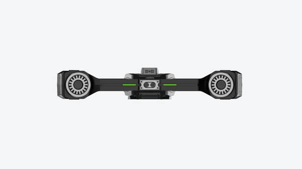
Scenario Snapshot
A practical way to read the article is through this scenario:
- The Spec Sheet Misconception That Derails Deep Cavi…: I’ve watched too many first-article inspection trials unravel because the team trusted a single accuracy number on…
- Why Standalone Specs Fail to Predict Deep Cavity Sc…: Spec sheet accuracy figures are almost always captured on flat, fully accessible calibration artifacts—not on the…
- Quality-Aligned Field Validation Checks for Deep Ca…: How do you verify a 3D scanning deep cavities solution actually delivers on spec sheet promises, instead of wastin…
For this discussion, “deep cavities” means high-aspect-ratio internal geometries: turbine blade cooling channels, engine block liner bores, orthopedic implant lumens, and downhole tool features where the depth-to-diameter ratio routinely exceeds 6:1. In these spaces, the laser spot elongates, beam steering becomes unstable, and the scanner’s own standoff works against it.
Why Standalone Specs Fail to Predict Deep Cavity Scan Performance
Spec sheet accuracy figures are almost always captured on flat, fully accessible calibration artifacts—not on the internal surfaces of a deep cavity where the scanner actually has to work. When you’re inspecting a recessed bore, an undercut groove, or a cast housing with a high depth-to-diameter ratio, that published 0.020 mm number becomes meaningless. The real physics of the scan take over.
Deployment Validation Checklist
| Focus Area | Decision Point | Deployment Note |
|---|---|---|
| Target part | Check size, surface condition, and key tolerances against the scan task | Run a full trial scan on a representative part |
| Data workflow | Verify point cloud, deviation map, and quality-report handoff | Confirm export formats and review ownership in advance |
| Shop-floor use | Review training, calibration, lighting, and working space | Keep the validation record as a repeatable inspection reference |
Line-of-sight blockages are the first and most obvious failure mechanism. A scanner can’t measure what it can’t see. The bottom of a deep cavity, the side walls beyond a shoulder, and the back face of an internal rib all sit in shadow zones where data simply drops out. If a spec sheet doesn’t document the system’s behavior at extreme viewing angles and standoff distances inside a constrained volume, you’re buying blind.
Marker placement amplifies the problem. Most tracking systems rely on a visible constellation of reference targets. Inside a deep cavity, there’s often no clean line of sight to enough markers, so the system loses its position lock. The resulting point cloud can show a false smoothness or a distorted contour that masks true dimensional errors.
Auditors later find that an out‑of‑tolerance groove diameter or a missed undercut never registered because the tracking drifted and the data was discarded.
Surface reflectivity inside cavities adds another layer of uncertainty. The same cast iron, polished steel, or carbon fiber interior that looks fine to the eye can confuse a scanner’s exposure logic. Dark, shiny surfaces create low‑signal or saturated patches, and the boundary between a valid scan and a noisy reconstruction becomes impossible to define from a spec sheet alone.
You’re left with a mesh that looks complete but doesn’t hold up to a CMM cross‑check.
As the aspect ratio climbs, the effective resolution at depth degrades. A scanner that resolves 0.05 mm on a flat gauge block may deliver only 0.2 mm or worse at the bottom of a 300‑mm‑deep cavity, because the projected pattern expands and the triangulation angle collapses.
INSVISION’s approach with V‑Track addresses this by maintaining a stable, external tracking reference that doesn’t depend on markers inside the cavity, but the principle remains: the geometry of the part dictates the real measurement limits, not the brochure.
Quality-Aligned Field Validation Checks for Deep Cavity Scanners
How do you verify a 3D scanning deep cavities solution actually delivers on spec sheet promises, instead of wasting hours on failed first-article inspections?
Too many quality teams rely on vendor calibration data that never translates to production parts with complex recessed features. ISO 9001/AS9100-aligned field validation cuts through marketing hype by tying tests directly to your workflow needs.
Test data completeness on your production parts at your target cavity aspect ratio, not generic test blocks. Run GR&R assessments on critical recessed features—internal groove diameters, step heights, seal land dimensions—to confirm consistent results across operators.
Evaluate fixturing and scan path maneuverability for your existing workcell, then review final meshes against GD&T callouts to ensure they fit your inspection reporting or reverse engineering workflows.

Spec sheet claims map directly to actionable tests: a maximum aspect ratio claim becomes a test on your deepest production cavity, while an accuracy spec requires GR&R on your tightest tolerance internal feature. INSVISION designs its V-Track 3D scanning system to support these checks, with metrics tied to real industrial use cases rather than lab-only conditions.
Fit-for-Purpose Selection Framework for Deep Cavity Scanning
Many inspection engineers assume that a scanner’s listed accuracy and point density will predict how well it handles deep cavities. That assumption falls apart the first time you try to hold a stable reference while probing a blind pocket six inches inside a casting.
The real selection metric is not the spec sheet headline—it is whether the system can maintain a reliable coordinate frame when the sensor head is completely hidden from the external tracking volume.
A fit-for-purpose framework starts by mapping the part geometry and production mix to the right sensing principle. Fixed structured light systems deliver excellent repeatability for small, high-volume cavity parts where a dedicated fixture keeps the part in a known position shot after shot.
The moment you move to large weldments, complex engine housings, or high-mix repair work, tracking-based 3D scanning becomes the better match. These systems let you move the scanner freely around the part, accessing multiple internal cavities without repositioning the entire assembly.
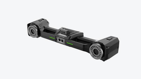
INSVISION’s V-Track tracking 3D scanning system is built around this access-first logic. Its marker-referenced tracking holds position accuracy even as the operator angles the scanner head into narrow openings, which directly satisfies the validation criterion of positional stability during multi-angle internal capture.
Consistent data density across a range of internal surface finishes—from as-cast to lightly machined—means you get a reviewable dataset without chasing parameter tweaks.
Practical Use Case Boundaries for Consistent Deep Cavity Scan Results
The assumption that a 3D scanner can simply “see” into any deep cavity and produce trustworthy data often leads to audit failures. Non-contact optical systems struggle where geometry blocks line-of-sight or surface finish scatters the laser unpredictably. For tracking-based setups like INSVISION’s V-Track, the most consistent, audit-ready results emerge within clear boundaries.
These systems are best suited for medium to large parts with multiple accessible deep cavities, where the optical tracker and handheld scanner maintain a stable reference without requiring part-mounted targets. Cavity aspect ratio is the real gatekeeper. A depth-to-width ratio beyond roughly 3:1 typically demands validation, because the scanner’s offset and viewing angle create shadow zones that degrade data at the bottom.
Surface finish matters just as much. As-cast, matte, or uniformly blasted cavity walls return clean profiles; mirror-like or oily surfaces can introduce noise that compromises a GD&T callout.
High-mix production environments with frequent fixture changes tip the decision toward tracking-based measurement, since the system adapts to the part rather than forcing the part into a fixed setup. But no spec sheet replaces a trial. Every deep cavity application requires a targeted validation sample run against the actual part geometry, surface condition, and tolerance requirements.
Quality leads who treat this as an evidence-gathering step, not a checkbox, get repeatable inspection data that holds up during a supplier audit.
Common Deep Cavity Scanning Misconceptions (Q&A)
Common Deep Cavity Scanning Misconceptions (Q&A)
Before teams formalize 3D scanning deep cavities into their quality workflow, most rely on spec sheet checklists to shortlist scanners — a habit that leads to costly mismatches when parts have tight, high-aspect-ratio cavities. Below are the most common questions quality and engineering teams ask during pre-purchase validation, each addressing a widespread myth about cavity scanning performance.
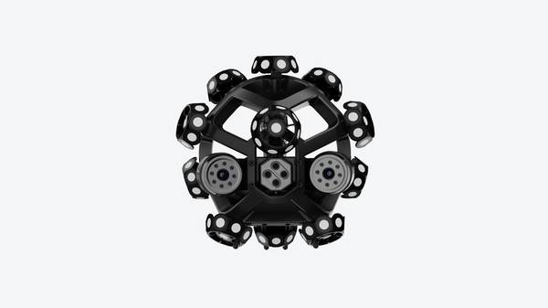
Q: Can any high-accuracy 3D scanner measure deep cavities?
A: No. The accuracy rating on a spec sheet only applies under lab-tested conditions, usually for flat, easily accessible surfaces within the scanner’s ideal working distance. Deep cavities create line-of-sight blocks, reduce light return to the sensor, and can push the working distance outside the rated range. All of these drag down real-world accuracy.
Many teams overlook minimum working distance and field of view constraints when reviewing specs, which is why sample part validation is non-negotiable for any cavity inspection use case.
Q: Do deep cavity scans always require surface spraying?
A: Not always. The need for spraying depends on part material, surface finish, and the scanner’s light source type. Shiny, reflective, or transparent cavity walls scatter structured light or laser signals, leaving gaps in the point cloud.
For most machined metal cavities with Ra values above 1.6, many scanners capture usable data without spraying, but teams should verify data completeness against critical GD&T callouts before skipping the step. Never assume a “no-spray” marketing claim applies to your specific part geometry.
Q: Is higher scanner resolution always better for deep cavity inspection?
A: No. Higher resolution delivers smaller point spacing, which can improve detail capture on fine cavity features, but it also ramps up scan time and file size, and can introduce excess noise if the sensor can’t maintain consistent light intensity deep inside the cavity.
For general cavity volume or positional tolerance checks, a lower resolution matched to the required tolerance band will deliver faster, more consistent results. Resolution only becomes a priority when inspecting features with tight form tolerances, like seal surfaces or thread roots.
Q: Can tracking-based scanners maintain accuracy inside narrow cavities?
A: It depends on the tracking system’s line-of-sight requirements and the cavity’s aspect ratio. Traditional external tracking systems rely on fixed cameras that can lose sight of scanner targets deep inside narrow cavities, leading to positional drift. INSVISION’s V-Track system uses a hybrid tracking approach that maintains target lock even in constrained spaces, cutting down drift in deep, narrow cavities.
Even so, teams should validate accuracy at the maximum cavity depth they need to inspect, using a calibrated depth artifact or production part with known reference points.
The core takeaway for quality teams is that reliable 3D scanning deep cavities doesn’t come down to a single spec sheet number. It requires matching scanner technology to your specific part geometry, tolerance requirements, and production environment, then validating performance with real production parts before rolling out the workflow.
This validation-first approach fits best for high-mix, high-tolerance parts in aerospace MRO, automotive powertrain, and medical device manufacturing, where cavity geometry directly impacts part function.
On site, teams should verify data completeness at maximum cavity depth, check repeatability across three consecutive scans, and confirm that all critical GD&T callouts have sufficient point density to meet ISO 17025 audit standards.
Hangzhou Insvision Technology Co., Ltd.
Address: Building 1, No. 1399 Liangmu Road, Yuhang District, Hangzhou, Zhejiang 311121, China
Copyright © Hangzhou Insvision Technology Co., Ltd. All rights reserved.
Copyright © Hangzhou Insvision Technology Co., Ltd. All rights reserved.